Specifications
Thermostat power requirements:
19-30 Vac 50 or 60 Hz; 2 VA ( RC & C ) Class 2
RC to RH jumper 2.0 Amps 48 VA maximum
0 °C to 50 °C ( 32 °F to 122 °F )
0% to 95% R.H. non-condensing
-30 °C to 50 °C ( -22 °F to 122 °F )
0% to 95% R.H. non-condensing
Local 10 K NTC thermistor
± 0.5 ° C ( ± 0.9 °F ) @ 21 °C ( 70 °F ) typical calibrated
Occupied and unoccupied setpoint range cooling:
12.0 to 37.5 °C ( 54 to 100 °F )
Occupied and unoccupied setpoint range heating:
4.5 °C to 32 °C ( 40 °F to 90 °F )
Room and outdoor air temperature range
-40 °C to 50 °C ( -40 °F to 122 °F )
Proportional band for room temperature control:
Factory set, heating and cooling at: 1.1°C ( 2.0°F )
Relay dry contact only across C terminal to DI1 or DI2
Each relay output: ( Y1, Y2, G, W1, W2 & AU )
30 Vac, 1 Amp. maximum
Economizer analog output rating:
0 to 10 Vdc into 2KΩ resistance min.
Economizer analog output accuracy:
18 gauge maximum, 22 gauge recommended
Approximate shipping weight:
Agency Approvals all models:
UL: UL 873 (US) and CSA C22.2 No. 24 (Canada), File
E27734 with CCN XAPX (US) and XAPX7 (Canada)
Industry Canada: ICES-003 (Canada)
Agency Approvals all models
FCC: Compliant to CFR 47, Part 15, Subpart B, Class A
(US)
CE: EMC Directive 89/336/EEC (Europe Union)
C-Tick: AS/NZS CISPR 22 Compliant (Australia / New
Zealand) Supplier Code Number N10696
Agency Approvals Wireless models
FCC: Compliant to: Part 15, Subpart C
THIS DEVICE COMPLIES WITH PART 15 OF THE FCC RULES. OPERATION IS SUBJECT TO THE
FOLLOWING TWO CONDITIONS: (1) THIS DEVICE MAY NOT CAUSE HARMFUL INTERFERENCE, AND (2)
THIS DEVICE MUST ACCEPT ANY INTERFERENCE RECEIVED, INCLUDING INTERFERENCE THAT MAY
CAUSE UNDESIRED OPERATION.
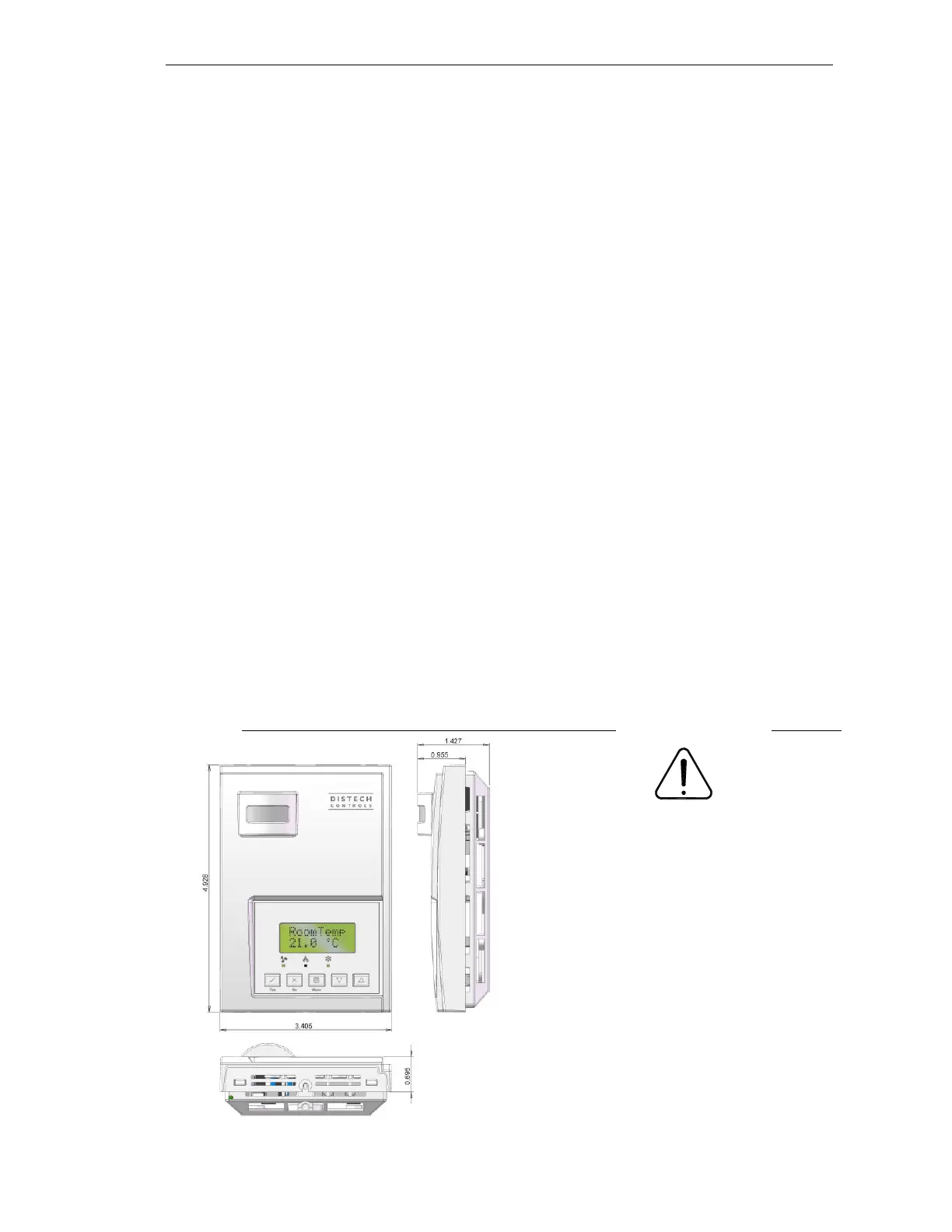
Drawing & dimensions
Fig.11 – Thermostat dimensions
Important notice
All
Allure
communicating
thermostats
controls are for use as operating
controls only and are not safety
devices. These instruments have
undergone rigorous tests and
verifications prior to shipment to
ensure proper and reliable
operation in the field. Whenever
a control failure could lead to
personal injury and/or loss of
property, it becomes the
responsibility of the user / installer
/ electrical system designer to
incorporate safety devices (
such as relays, flow switch,
thermal protections, etc…) and/or
alarm system to protect the entire
system against such catastrophic
failures. Tampering of the
devices or miss application of the
device
will void warranty.
HP Series Thermostats_IG_11_EN