PROTOCOL AND OPERATIONAL WORK
Displays for series DT-203NN, DT-105NN and DT-110NN
To define the input/output address range in the PLC, drag “Module” to the address fields of
slot 1 in the device and fix the start addresses corresponding to input and output according
your available addresses.
Depending on the display model the output address range will be sized accordingly to the
number of lines and characters. With regard to the input addresses, only 2 bytes will be
used for return control information in future updates of the product (actually no data is
returned).
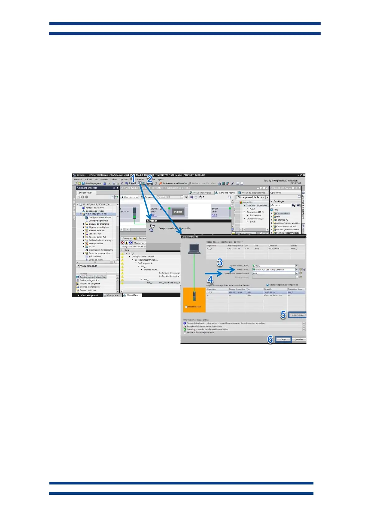
5. Compile and update the project in the PLC
With all the elements added and configured, compile the project (1). Once verified that
there are no compilation errors, load the configuration into the PLC (2).
To download the configuration to the device, select the network card in the “PG/PC
interface” field (3) at “Extended download to device” window, and establish the identifier
of the Profinet network (PN/IE_1 in this example, See Fig. 11) in the “Connection to
subnet” field (4).
Press “Refresh” (5), to detect the PLC and “Load” (6) to start the PLC programming.
Fig. 13 Compilation and configuration upload in the PLC
 Loading...