Do you have a question about the dixell Ichill 260L_D DUO and is the answer not in the manual?
Details chiller management, compressor start-up, capacity step control, and regulation features.
Essential safety guidelines for proper installation and operation of the controller.
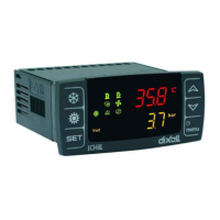
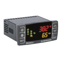
Explains the function of LEDs on the IC260L/IC261L models.
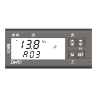
Describes LED indicators and key functions for remote keyboards.
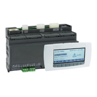
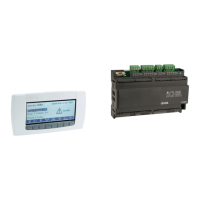
Details relays, inputs, outputs, and connections for the Ichill 260L.
Details relays, inputs, outputs, and connections for the Ichill 261L.
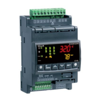
Details connections and specifications for the Ichill 260D model.
Details connections and specifications for the Ichill 261D model.
Illustrates wiring diagrams for temperature/pressure probes and digital inputs.
Shows wiring diagrams for pressure and ratiometric transducers.
Illustrates PWM and 0-10Vdc signal connections for fan speed control.
Wiring diagrams for damper control and managing external relays.
Illustrates connections for programming tools and monitoring interfaces.
Details RS485 communication and remote keyboard wiring.
Shows the wiring diagram for connecting remote panels to the unit.
Lists parameters and options for configuring analog inputs (Pb1-Pb10).
Lists available configurations for 18 digital inputs (Id1-Id18).
Lists parameters for configuring various digital output relay functions.
Configures proportional outputs for condenser fan speed control.
Explains parameter CF79 for selecting the unit's operating mode.
Details automatic mode selection based on external temperature.
Setting custom read-outs for the top display using dP01.
Setting custom read-outs for the bottom display using dP02.
Procedures for viewing and resetting alarms from the list.
Manual reset procedures for compressor overload alarms.
Details parameters for chiller and heat pump setpoints and bands.
Details direct, part winding, and star-delta start-up configurations.
Table of parameters related to inverter compressor control.
Details pump down modes enabled by low pressure switch.
Details pump down modes using low pressure probes.
Parameters CF68 and CF69 for fan signal selection.
FA01 and FA02 parameters defining fan behavior.
Selecting probes for anti-freeze/boiler heater control in Chiller mode.
Selecting probes for anti-freeze/boiler heater control in Heat Pump mode.
Conditions required to enable the defrost function.
Explanation of the dF01 parameter for defrost modes.
Descriptions of defrost parameters dF01 through dF05.
Detailed descriptions of defrost parameters dF06 through dF16.
Conditions for enabling and disabling sanitary hot water production.
Sequence of operations when producing hot water.
Operation sequence for gas circuit valves when producing hot water.
Operation sequence for gas circuit valves when producing cold water.
Details parameters for free cooling setup.
Classifying alarms by type (unit, circuit, compressor).
Explains automatic and manual reset conditions for alarms.
Table of parameters related to thermoregulation.
Parameters for configuring display read-outs.
Parameters for unit type, selection, and compressor configuration.
Parameters for configuring analog inputs.
Parameters related to dynamic setpoint adjustments.
Parameters for energy saving and RTC functions.
Parameters for compressor rack configuration.
Parameters related to compressor operation timing.
Parameters for compressor OFF delay, capacity control, and start-up.
Parameters for evaporator pump operation and timing.
Parameters for condenser pump operation and timing.
Parameters for pump down operating modes and timing.
Parameters for inverter compressor control.
Parameters for 4-way valve, compressor capacity, and fan speed control.
Parameters for condenser fan configuration and operation mode.
Parameters for fan speed control and operation modes.
Parameters for antifreeze, integration, and boiler heaters.
Parameters for defrost modes, timing, and circuit logic.
Parameters related to fan control, forced defrost, and circuit modes.
Parameters for configuring the heat recovery function.
Parameters for sanitary water regulation and anti-legionella function.
Parameters for free cooling operation.
Parameters for configuring the anti-legionella cycle.
Parameters for configuring various alarms and their behavior.
Parameters for alarm relay, password, thermal, oil, and flow alarms.
Parameters for high pressure, flow, water temperature, and sanitary water alarms.
Specifies panel cut-out dimensions and mounting instructions.
Mounting instructions for DIN format series.
Panel cut-out dimensions for vertical boards.
Details terminal blocks, connectors, and optional kits.
Physical and electrical specifications for Ichill 260L/261L.
Physical and electrical specifications for Ichill 260D/261D.
Details display, connections, and power supply specifications.
Specifications for probes, inputs, outputs, and operating conditions.
| Brand | dixell |
|---|---|
| Model | Ichill 260L_D DUO |
| Category | Controller |
| Language | English |