1592009241 XW40L-V GB r1.0 04.05.2011 XW40L – XW40V 3/4
6.1 DOOR SWITCH INPUT (I2F = DOR)
It signals the door status and the corresponding relay output status through the “odc” parameter:
no, Fan = normal (any change);
CPr, F_C = Compressor OFF;
Since the door is opened, after the delay time set through parameter “dOA”, the alarm output is enabled
and the display shows the message “dA”. The alarm stops as soon as the external digital input is
disabled again. During this time and then for the delay “dot” after closing the door, the high and low
temperature alarms are disabled.
6.2 GENERIC ALARM (I2F = EAL)
As soon as the digital input is activated the unit will wait for “did” time delay before signalling the “EAL”
alarm message. The outputs status don’t change. The alarm stops just after the digital input is de-
activated.
6.3 SERIOUS ALARM MODE (I2F = BAL)
When the digital input is activated, the unit will wait for “did” delay before signalling the “BAL” alarm
message. The relay outputs are switched OFF. The alarm will stop as soon as the digital input is de-
activated.
6.4 PRESSURE SWITCH (I2F = PAL)
If during the interval time set by “did” parameter, the pressure switch has reached the number of
activation of the “nPS” parameter, the “PAL” pressure alarm message will be displayed. The
compressor and the regulation are stopped. When the digital input is ON the compressor is always OFF.
If the nPS activation in the did time is reached, switch off and on the instrument to restart
normal regulation.
6.5 START DEFROST (I2F = DFR)
It executes a defrost if there are the right conditions. After the defrost is finished, the normal regulation
will restart only if the digital input is disabled otherwise the instrument will wait until the “Mdf” safety time
is expired.
6.6 ENERGY SAVING (I2F = ES)
The Energy Saving function allows to change the set point value as the result of the SET+ HES
(parmeter) sum. This function is enabled until the digital input is activated.
6.7 REMOTE ON/OFF (I2F = ONF)
This function allows to switch ON and OFF the instrument.
6.8 DIGITAL INPUTS POLARITY
The digital input polarity depends on the “I2P” parameters.
CL : the digital input is activated by closing the contact.
OP : the digital input is activated by opening the contact
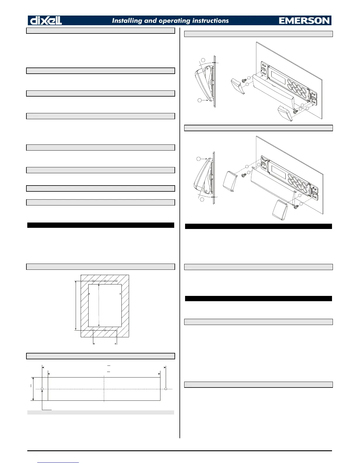
7. INSTALLATION AND MOUNTING
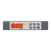
Instrument XW40L shall be mounted on vertical panel, in a 150x31 mm hole, and fixed using two screws
3 x 2mm. To obtain an IP65 protection grade use the front panel rubber gasket (mod. RG-L).
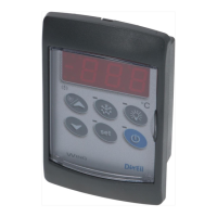
Instrument XW40V shall be mounted on vertical panel, in a 72x56 mm hole, and fixed using screws 3
x 2mm. To obtain an IP65 protection grade use the front panel rubber gasket (mod. RGW-V).
The temperature range allowed for correct operation is 0 - 60 °C. Avoid places subject to strong
vibrations, corrosive gases, excessive dirt or humidity. The same recommendations apply to probes. Let
the air circulate by the cooling holes.
7.1 XW40V: CUT OUT
56
7
8. ELECTRICAL CONNECTIONS
The instruments are provided with screw terminal block to connect cables with a cross section up to 2,5
mm
2
for the digital and analogue inputs. Relays and power supply have a Faston connection (6,3mm).
Heat-resistant cables have to be used. Before connecting cables make sure the power supply complies
with the instrument’s requirements. Separate the probe cables from the power supply cables, from the
outputs and the power connections. Do not exceed the maximum current allowed on each relay, in case
of heavier loads use a suitable external relay.
N.B. Maximum current allowed for all the loads is 20A.
8.1 PROBE CONNECTIONS
The probes shall be mounted with the bulb upwards to prevent damages due to casual liquid infiltration.
It is recommended to place the thermostat probe away from air streams to correctly measure the
average room temperature. Place the defrost termination probe among the evaporator fins in the coldest
place, where most ice is formed, far from heaters or from the warmest place during defrost, to prevent
premature defrost termination.
9. USE OF THE PROGRAMMING “HOT KEY “
The Wing units can UPLOAD or DOWNLOAD the parameter list from its own E2 internal memory to the
“Hot Key” and vice-versa.
9.1 DOWNLOAD (FROM THE “HOT KEY” TO THE INSTRUMENT)
1. Turn OFF the instrument by means of the ON/OFF key, remove the TTL serial cable if present,
insert the “Hot Key” and then turn the Wing ON.
2. Automatically the parameter list of the “Hot Key” is downloaded into the Wing memory, the
“DoL” message is blinking. After 10 seconds the instrument will restart working with the new
parameters.
3. Turn OFF the instrument remove the “Hot Key”, plug in the TTL serial cable, then turn it ON
again.
At the end of the data transfer phase the instrument displays the following messages:
“end “ for right programming. The instrument starts regularly with the new programming.
“err” for failed programming. In this case turn the unit off and then on if you want to restart the download
again or remove the “Hot key” to abort the operation.
9.2 UPLOAD (FROM THE INSTRUMENT TO THE “HOT KEY”)
1. Turn OFF the instrument by means of the ON/OFF key and remove the TTL serial cable if
present; then turn it ON again.
2. When the Wing unit is ON, insert the “Hot key” and push o key; the "uPL" message
appears.
3. Push “SET” key to start the UPLOAD; the “uPL” message is blinking.
4. Turn OFF the instrument remove the “Hot Key”, plug in the TTL serial cable, then turn it ON
again.
At the end of the data transfer phase the instrument displays the following messages:
“end “ for right programming.
“err” for failed programming. In this case push “SET” key if you want to restart the programming again or
remove the not programmed “Hot key”.
 Loading...