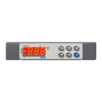
1592009241 XW40L-V GB r1.0 04.05.2011 XW40L – XW40V 4/4
10. ALARM SIGNALS
Message
Cause Outputs
“P1” Thermostat probe failure
Alarm output ON; Compressor output according to
parameters “COn” and “COF”
“P2” Evaporator probe failure Alarm output ON; Other outputs unchanged
“HA” Maximum temperature alarm Alarm output ON; Other outputs unchanged
“LA” Minimum temperature alarm Alarm output ON; Other outputs unchanged
“EE” Data or memory failure Alarm output ON; Other outputs unchanged
“dA” Door switch alarm Alarm output ON; Other outputs unchanged
“EAL” External alarm Alarm output ON; Other outputs unchanged
“BAL” Serious external alarm Alarm output ON; Other outputs OFF
“PAL” Pressure switch alarm Alarm output ON; Other outputs OFF
The alarm message is displayed until the alarm condition is recovery.
All the alarm messages are showed alternating with the room temperature except for the “P1” which is
flashing. To reset the “EE” alarm and restart the normal functioning press any key, the “rSt” message is
displayed for about 3s.
10.1 SILENCING BUZZER
Once the alarm signal is detected the buzzer can be silenced by pressing any key.
10.2 “EE” ALARM
The dIXEL instruments are provided with an internal check for the data integrity. Alarm “EE” flashes
when a failure in the memory data occurs. In such cases the alarm output is enabled.
10.3 ALARM RECOVERY
Probe alarms : “P1” (probe1 faulty), “P2” ; they automatically stop 10s after the probe restarts normal
operation. Check connections before replacing the probe.
Temperature alarms “HA” and “LA” automatically stop as soon as the thermostat temperature returns
to normal values or when the defrost starts.
Door switch alarm “dA” stop as soon as the door is closed.
External alarms “EAL”, “BAL” stop as soon as the external digital input is disabled
Pressure switch alarm “PAL” alarm is recovered by switching OFF the instrument.
11. TECHNICAL DATA
Housing: self extinguishing ABS.
Case
XW40L: facia 38x185 mm; depth 76mm
XW40V: facia 100x64 mm; depth 76mm
Mounting
XW40L: panel mounting in a 150x31 mm panel cut-out with two screws. 3 x 2mm. Distance
between the holes 165mm
XW40L: panel mounting in a 56x72 mm panel cut-out with two screws. 3x2mm. Distance
between the holes 40mm
Protection: IP20.
Frontal protection: IP65 with optional frontal gasket mod RG-L (XW40L); RGW-V (XW40V).
Connections: Screw terminal block 2,5 mm
2
heat-resistant wiring and 6,3mm Faston
Power supply: 230Vac or. 110Vac 10%
Power absorption: 7VA max.
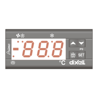
Display: 3 digits, red LED, 14,2 mm high.
Inputs: 2 NTC or PTC probes
Digital input: 1 free voltage
Relay outputs: Total current on loads MAX. 20A
compressor: relay SPST 20(8) A, 250Vac or. SPST 8(3) A, 250Vac
light: XW40L: relè SPDT 8(3) A, 250Vac; XW40V: relè SPST 16(6) A, 250Vac
defrost: relay SPST 8(3) A, 250Vac
Other output : alarm buzzer
Data storing: on the non-volatile memory (EEPROM).
Kind of action: 1B.
Pollution grade: normal
Software class: A.
Operating temperature: 0÷60 °C.
Storage temperature: -25÷60 °C.
Relative humidity: 2085% (no condensing)
Measuring and regulation range:
PTC probe: -50÷150°C (-58÷302°F)
NTC probe: -40÷110°C (-58÷230°F)
Resolution: 0,1 °C or 1°C or 1 °F (selectable).
Accuracy (ambient temp. 25°C): ±0,5 °C ±1 digit
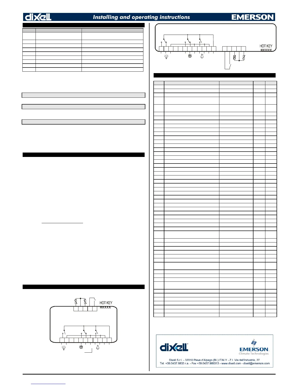
12. CONNECTIONS
Input
20A
250Vac
MAX
20A
8A
250Vac
16A
250Vac
XW40L
Def.
20A
250Vac
MAX
20A
8A
250Vac
Comp
Line
Neutral
8A
250Vac
13141516125 6 7 8 9 10 111 2 3 4 17
Luce
13. DEFAULT SETTING VALUES
Label
Set Set point LS÷US -5/0 Pr1
Hy Differential 0,1÷25,5 °C / 1÷45°F 2/4 Pr1
LS Minimum set point -50,0°C÷SET / -
58°F÷SET
-30/-22 Pr2
US Maximum set point SET ÷ 110°C / SET ÷
230°F
20/68 Pr2
OdS Outputs activation delay at start up 0÷255 min. 0 Pr2
AC Anti-short cycle delay 0÷30 min. 1 Pr1
CCt Compressor ON time during fast freezing 0 ÷ 23h 50 min. 0.0 Pr2
COn Compressor ON time with faulty probe 0÷255 min. 15 Pr2
COF Compressor OFF time with faulty probe 0÷255 min. 30 Pr2
DISPLAY
CF Temperature measurement unit °C ÷ °F °C/F Pr2
rES Resolution (integer/decimal point) in ÷ de dE/- Pr1
Lod Local display P1 ÷ 1r2 P1 Pr2
DEFROST
tdF Defrost type rE, rT, in rE Pr2
EdF Defrost mode In, Sd in Pr2
SdF Set point for SMART DEFROST -30 ÷ +30°C / -22÷+86°F 0/32 Pr2
dtE Defrost termination temperature -50,0÷110°C/ -58÷230°F 8/46 Pr1
IdF Interval between defrost cycles 1÷120h 6 Pr1
MdF (Maximum) length for 1° defrost 0÷255 min. 30 Pr1
dFd Displaying during defrost rt, it, SEt, dEF, dEG it Pr2
dAd MAX display delay after defrost 0÷255 min. 30 Pr2
dSd Delay before defrost 0÷255 min. 0 Pr2
Fdt Draining time 0÷60 min. 0 Pr2
dPO First defrost after start up n ÷ y n Pr2
dAF Defrost delay after fast freezing 0 ÷ 23h 50 min. 0.0 Pr2
ALARMS
ALC Temperature alarms configuration rE÷Ab Ab Pr2
ALU MAXIMUM temperature alarm -50,0÷110°C/ -58÷230°F 110/230
Pr1
ALL minimum temperature alarm -50,0÷110°C/ -58÷230°F -40/-40 Pr1
AFH Temperature alarm differential 0,1÷25,5 °C / 1÷45°F 2/4 Pr2
ALd Temperature alarm delay 0÷255 min. 15 Pr2
dAO Delay of temperature alarm at start up 0 ÷ 23h 50 min. 1,3 Pr2
EdA Alarm delay at the end of defrost 0÷255 min. 30 Pr2
dot
Delay of temperature alarm after closing the
door
0÷255 min. 15 Pr2
dOA Open door alarm delay 0÷255 min. 15 Pr2
nPS Pressure switch number 0÷15 0 Pr2
ANALOGUE INPUTS
Ot Thermostat probe calibration -12,0÷12,0°C / -21÷21°F 0/0 Pr1
OE Evaporator probe calibration -12,0÷12,0°C / -21÷21°F 0/0 Pr2
P2P Evaporator probe presence n ÷ y y Pr2
HES
Temperature increasing during the Energy
Saving cycle
-30÷30°F/-54÷54°F 0/0 Pr2
Odc Open door control no, Fan, CPr, F_C no Pr2
I2P Configurable digital input polarity CL÷OP CL Pr2
i2F Digital input configuration dor, EAL, bAL, PAL, dFr,
AUS, ES, OnF
dor Pr2
dId Digital input alarm delay 0÷255 min. 5 Pr2
Pbc Kind of probe PbC, ntc ntc/Ptc Pr2
rEL Software release - - - 2.0 Pr2
Ptb Map code - - - - - - Pr2
Prd Probes display Pb1÷Pb3 - - - Pr2
Pr2 Access parameter list - - - - - - Pr2
 Loading...