EasyManua.ls Logo

dixell XM470K User Manual

dixell XM470K
6 pages
To Next Page IconTo Next Page
Page #1 background imageLoading...
Page #1 background image
Dixell
Installing and Operating Instructions
rel.1.0 –07/03/2002 - cod.
1592013010
1592013010 XM470K GB XM470K 1/6
XM470K
1. GENERAL WARNING
1.1 PLEASE READ BEFORE USING THIS MANUAL
This manual is part of the product and should be kept near the instrument for easy and quick
reference.
The instrument shall not be used for purposes different from those described hereunder. It cannot
be used as a safety device.
Check the application limits before proceeding.
1.2
SAF
ETY PRECAUTIONS
Check the supply voltage is correct before connecting the instrument.
Do not expose to water or moisture: use the controller only within the operating limits avoiding
sudden temperature changes with high atmospheric humidity to prevent formation of
condensation
Warning: disconnect all electrical connections before any kind of maintenance.
Fit the probe where it is not accessible by the End User. The instrument must not be opened.
In case of failure or faulty operation send the instrument back to the distributor or to “Dixell s.r.l.”
(see address) with a detailed description of the fault.
Consider the maximum current which can be applied to each relay (see Technical Data).
Ensure that the wires for probes, loads and the power supply are separated and far enough from
each other, without crossing or intertwining.
In case of applications in industrial environments, the use of mains filters (our mod. FT1) in parallel
with inductive loads could be useful.
2. GENERAL DESCRIPTION
Model XM470K is microprocessor based controllers suitable for applications on medium or low
temperature multiplexed cabinets made of up to 5 units. It can be inserted in a LAN of up to 5 different
sections which can operate, depending on the programming, as stand alone controllers or following the
commands coming from one of the other sections. XM470K is provided with five relay outputs to control
the solenoid valve, defrost - which can be either electrical or hot gas - the evaporator fans, the lights,
and an auxiliary output. They are also provided with three NTC probe inputs, one for temperature
control, one to control the defrost end temperature of the evaporator and the third, optional, for the
display. There are two digital inputs (free contact) one for the start of an energy saving cycle and one
fully configurable by parameter.
Two LAN output allows an easy connection between the controllers and a TTL connector for quick
programming by means of an Hot Key is also available. Direct serial output RS485 ModBUS-RTU
compatible and internal RTC are available as options.
3. CONTROLLING LOADS
3.1 THE SOLENOID VALVE
The regulation is performed according to the temperature measured by the thermostat probe with a
positive differential from the set point: if the temperature increases and reaches set point plus differential
the solenoid valve is opened and then closed when the temperature reaches the set point value again.
In case of fault in the thermostat probe the opening and closing of the solenoid valve are timed through
parameters “COn” and “COF”.
3.2 DEFROST
Two defrost modes are available through the tdF” parameter: defrost with electrical heater and hot gas
defrost. The defrost interval is control by means of parameter “EdF”: (EdF = rtc) the defrost is made in
real time depending on the hours set in the parameters Ld1..Ld8 on workdays and in Sd1…Sd8 in
holidays; (EdF = in) the defrost is made every “IdF” time, (EdF=Sd) the interval “IdF” is calculate through
Smart Defrost algorithm (only when the SOLENOID VALVE is ON and the evaporator temperature is
bigger than “SdF” parameter).
At the end of defrost the drip time is controlled through the “Fdt” parameter.
The starting of a defrost cycle can be operated locally (manual activation by means of the keyboard or
digital input or end of interval time) or the command can come from the Master defrost unit of the LAN.
In this case the controller will operate the defrost cycle following the parameters it has programmed but,
at the end of the drip time, will wait that all the other controllers of the LAN finish their defrost cycle
before to re-start the normal regulation of the temperature.
Every time any of the controller of the LAN begin a defrost cycle it issue the command into the network
making all the other controllers start their own cycle. This allows a perfect synchronisation of the defrost
in the whole multiplexed cabinet
3.3 CONTROL OF EVAPORATOR FANS
The fan control mode is selected by means of the “FnC” parameter:
C-n = running with the solenoid valve, OFF during the defrost;
C-y = running with the solenoid valve, ON during the defrost;
O-n = continuous mode, OFF during the defrost;
O-y = continuous mode, ON during the defrost;
An additional parameter “FSt” provides the setting of temperature, detected by the evaporator probe,
above which the fans are always OFF. This can be used to make sure circulation of air only if his
temperature is lower than set in “FSt”.
3.4 AUXILIARY OUTPUT
The auxiliary output is switch ON and OFF by means of the corresponding button on the keyboard.
4. KEYBOARDS
There are two kind of keyboard available for the XM470K controller:.
T840: 8 Keys, horizontal shape (185x38mm).
V840: 8 Keys, vertical shape (64x100mm).
To display and modify target set point; in programming mode it selects a parameter or
confirm an operation.
By holding it pressed for 3s when max or min temperature is displayed it will be erased.
By pressing it when the current time is displayed, it allows the User to re-set the current time
and three holidays.
To see the max. stored temperature; in programming mode it browses the parameter codes
or increases the displayed value.
By holding it pressed for 3s the give access to the “Section” menù.
To see the min stored temperature; in programming mode it browses the parameter codes or
decreases the displayed value.
By holding it pressed for 3s the current time is displayed and it permits the User to enter
Energy saving, Defrost and Clock parameter menu.
By holding it pressed for 3s the defrost is started.
By pressing it when the current time is displayed, it allows the User to set defrost times.
Switch ON and OFF the cold room light.
By holding it pressed for 3s Energy Saving function is started or stopped.
By holding it pressed for 6s, the Holiday function is started or stopped.
By pressing it when the current time is displayed, it allows the User to set Energy Saving
times.
Switch ON and OFF the auxiliary output.
Switch ON and OFF the instrument.
KEY COMBINATIONS
+
To lock and unlock the keyboard.
+
To enter the programming mode.
+
To exit the programming mode.
4.1 USE OF LEDS
Each LED function is described in the following table.
LED MODE Function
ON The SOLENOID VALVE is running
FLASHING
- Programming Phase (flashing with LED
)
- Anti-short cycle delay enabled
Question and Answer IconNeed help?

Do you have a question about the dixell XM470K and is the answer not in the manual?

dixell XM470K Specifications

General IconGeneral
ModelXM470K
SeriesXM
Output TypeRelay
Digital Inputs2
Digital CommunicationRS485
CommunicationModbus RTU
DisplayLCD
Power Consumption5W
Protection DegreeIP20
TypeController
Input TypeNTC
Humidity20% to 90% RH non-condensing
MountingPanel Mount
Weight200g

Summary

GENERAL WARNING

PLEASE READ BEFORE USING THIS MANUAL

Important safety and usage instructions to be read before operating the device.

SAFETY PRECAUTIONS

Crucial safety measures to prevent damage or injury during installation and operation.

GENERAL DESCRIPTION

GENERAL DESCRIPTION

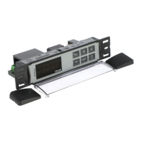
Overview of the XM470K model and its capabilities.

CONTROLLING LOADS

THE SOLENOID VALVE

Explanation of solenoid valve operation based on temperature and parameters.

DEFROST

Details on defrost modes, intervals, and end-of-defrost procedures.

CONTROL OF EVAPORATOR FANS

How evaporator fans are controlled based on parameters and temperature.

AUXILIARY OUTPUT

Control of the auxiliary output via the keyboard button.

KEYBOARDS

USE OF LEDS

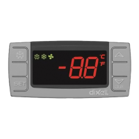
Explains the function of each LED indicator on the controller.

HOW TO SEE THE MIN TEMPERATURE

HOW TO SEE THE MIN TEMPERATURE

Procedure to view the minimum recorded temperature.

HOW TO SEE THE MAX TEMPERATURE

HOW TO SEE THE MAX TEMPERATURE

Procedure to view the maximum recorded temperature.

HOW TO RESET THE MAX AND MIN TEMPERATURE RECORDED

HOW TO RESET THE MAX AND MIN TEMPERATURE RECORDED

Steps to reset stored maximum and minimum temperature values.

HOW TO SEE AND MODIFY THE SET POINT

HOW TO SEE AND MODIFY THE SET POINT

How to view and change the target temperature set point.

TO START A MANUAL DEFROST

TO START A MANUAL DEFROST

Instructions for initiating a manual defrost cycle.

TO ENTER IN PARAMETERS LIST "PR1"

TO ENTER IN PARAMETERS LIST "PR1"

How to access the user-accessible parameter list (PR1).

TO ENTER IN PARAMETERS LIST "PR2"

TO ENTER IN PARAMETERS LIST "PR2"

How to access the protected parameter list (PR2) using a security code.

HOW TO CHANGE THE PARAMETER VALUE

HOW TO CHANGE THE PARAMETER VALUE

General procedure for modifying parameter values.

HOW TO LOCK THE KEYBOARD

HOW TO LOCK THE KEYBOARD

Method to lock the keyboard to prevent unintended changes.

ON/OFF FUNCTION

ON/OFF FUNCTION

How to turn the instrument ON or OFF using the dedicated key.

TO SEE THE PROBE VALUES

TO SEE THE PROBE VALUES

Procedure to display the values of connected probes.

THE SECTION MENU

THE SECTION MENU

Explanation of the Section menu for LAN configuration and control.

REAL TIME CLOCK FUNCTIONS

TO SEE THE CURRENT TIME AND DAY

How to view the current time and day.

TO SET THE TIME AND THE WEEKLY HOLIDAYS

Procedure to set the real-time clock and define holiday periods.

TO SET THE DEFROST TIMES

How to set specific times for defrost cycles.

TO SET THE ENERGY SAVING TIMES

How to configure the timing for energy-saving functions.

TO START HOLIDAY FUNCTION BY USING THE KEYBOARD

How to manually activate the holiday function via the keyboard.

PARAMETER LIST

REGULATION

Parameters related to temperature regulation and set points.

DISPLAY

Parameters affecting the display unit and probe selection.

DEFROST

Parameters for configuring defrost type, mode, and timing.

FANS

Parameters for controlling evaporator fan operation.

ALARMS

Parameters for configuring temperature alarms and delays.

ANALOGUE INPUTS

Parameters for calibrating probe inputs.

PROBE INPUTS

Parameters related to probe presence and calibration.

DIGITAL INPUTS

Parameters for configuring digital input functions and polarity.

TIME AND WEEKLY HOLIDAYS

Parameters for setting the clock and defining holiday schedules.

ENERGY SAVING TIMES

Parameters for setting energy saving cycle start and duration.

DEFROST TIMES

Parameters for setting specific defrost start times for workdays and holidays.

LAN CONFIGURATION

Parameters for configuring the Local Area Network (LAN) settings.

OTHER

Miscellaneous parameters like RS485 address and software release.

INSTALLATION AND MOUNTING

T840-CUT OUT

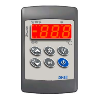
Dimensions and mounting instructions for the T840 keyboard.

T840 MOUNTING WITH KEYBOARD COVER OPENING DOWNWARD

Specific mounting detail for the T840 keyboard.

T840 MOUNTING WITH KEYBOARD COVER OPENING UPWARD

Specific mounting detail for the T840 keyboard.

V840- CUT OUT

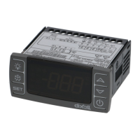
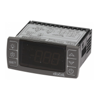
Dimensions and mounting instructions for the V840 keyboard.

ELECTRICAL CONNECTIONS

PROBE CONNECTIONS

Guidelines for connecting temperature probes correctly.

RS485 SERIAL LINE

RS485 SERIAL LINE

Information on connecting the XM470K to an RS485 serial line for monitoring.

USE OF THE PROGRAMMING "HOT KEY "

DOWNLOAD (FROM THE "HOT KEY" TO THE INSTRUMENT)

Procedure to download parameters from a Hot Key to the instrument.

UPLOAD (FROM THE INSTRUMENT TO THE "HOT KEY")

Procedure to upload parameters from the instrument to a Hot Key.

ALARM SIGNALS

LOCAL ALARMS

Details on local alarm messages, their causes, and output behavior.

REMOTE ALARMS

Information about remote alarms related to the LAN connection.

SILENCING BUZZER / ALARM RELAY OUTPUT

How to silence audible alarms and control relay outputs.

"EE" ALARM

Explanation of the EE alarm indicating internal memory failure.

ALARM RECOVERY

How different types of alarms are reset or recover.

CONNECTIONS

XM470K

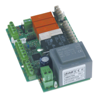
Wiring diagram and connection points for the XM470K controller.

DEFAULT SETTING VALUES

REGULATION

Default values for regulation parameters.

DISPLAY

Default values for display parameters.

DEFROST

Default values for defrost parameters.

FANS

Default values for fan control parameters.

ALARMS

Default values for alarm parameters.

ANALOGUE INPUTS

Default values for analogue input calibration.

PROBE INPUTS

Default values for probe related parameters.

DIGITAL INPUTS

Default values for digital input configuration.

TIME AND WEEKLY HOLIDAYS

Default values for time and holiday settings.

ENERGY SAVING TIMES

Default values for energy saving time settings.

DEFROST TIMES

Default values for defrost start times.

LAN CONFIGURATION

Default values for LAN settings.

Related product manuals