Dixell
Installing and Operating Instructions
1592007230
1592007230 XR40C GB r1.0 15.05.2003 XR40C 3/4
• Ptb Parameter table code: readable only.
8. DIGITAL INPUT
The free contact digital input is programmable in five different configurations by
the “i1F” parameter.
8.1 DOOR SWITCH INPUT (i1F = dor)
It signals the door status and the corresponding relay output status through the
“odc” parameter:
no, Fan = normal (any change);
CPr, F_C = Compressor OFF;
Since the door is opened, after the delay time set through parameter “did”, the
door alarm is enabled, the display shows the message “dA” and the regulation
restarts. The alarm stops as soon as the external digital input is disabled again.
With the door open, the high and low temperature alarms are disabled.
8.2 GENERIC ALARM (i1F = EAL)
As soon as the digital input is activated the unit will wait for “did” time delay before
signalling the “EAL” alarm message. The outputs status don’t change. The alarm
stops just after the digital input is de-activated.
8.3 SERIOUS ALARM MODE (i1F = bAL)
When the digital input is activated, the unit will wait for “did” delay before
signalling the “CA” alarm message. The relay outputs are switched OFF. The
alarm will stop as soon as the digital input is de-activated.
8.4 PRESSURE SWITCH (i1F = PAL)
If during the interval time set by “did” parameter, the pressure switch has reached
the number of activation of the “nPS” parameter, the “CA” pressure alarm
message will be displayed. The compressor and the regulation are stopped. When
the digital input is ON the compressor is always OFF.
If the nPS activation in the did time is reached, switch off and on the
instrument to restart normal regulation.
8.5 START DEFROST (i1F = dFr)
It starts a defrost if there are the right conditions. After the defrost is finished, the
normal regulation will restart only if the digital input is disabled otherwise the
instrument will wait until the “MdF” safety time is expired.
8.6 INVERSION OF THE KIND OF ACTION: HEATING-
COOLING (i1F = Htr)
This function allows to invert the regulation of the controller: from cooling to
heating and viceversa.
8.7 DIGITAL INPUTS POLARITY
The digital input polarity depends on the “i1P” parameter.
i1P=CL: the input is activated by closing the contact.
i1P=OP: the input is activated by opening the contact
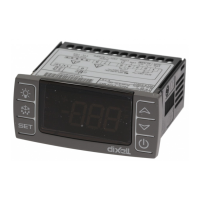
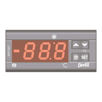
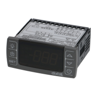
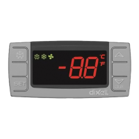
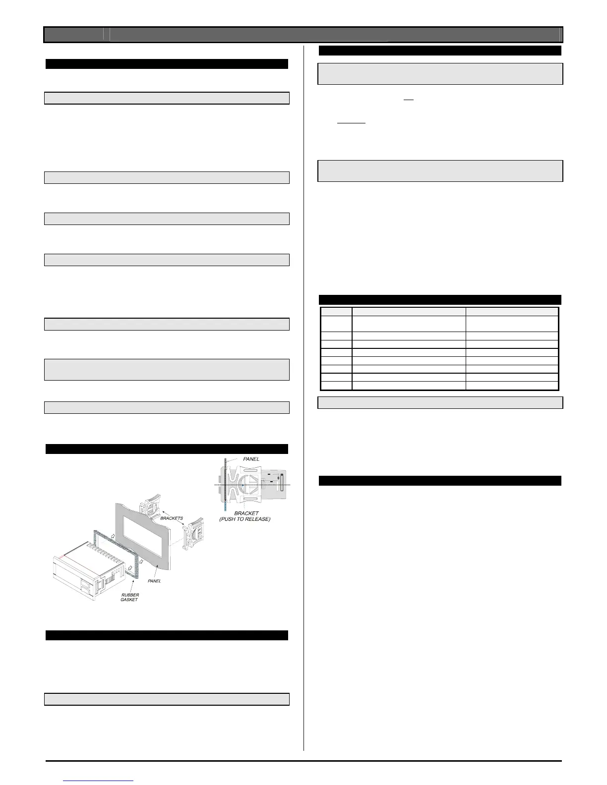
9. INSTALLATION AND MOUNTING
Instrument XR40C shall be mounted on vertical panel,
in a 29x71 mm hole, and fixed using the special bracket
supplied.
To obtain an IP65 protection grade use the front panel
rubber gasket (mod. RG-C) as shown in figure.
The temperature range allowed for correct operation is 0÷60 °C. Avoid places
subject to strong vibrations, corrosive gases, excessive dirt or humidity. The same
recommendations apply to probes. Let air circulate by the cooling holes.
10. ELECTRICAL CONNECTIONS
The instrument is provided with screw terminal block to connect cables with a
cross section up to 2,5 mm
2
. Before connecting cables make sure the power
supply complies with the instrument’s requirements. Separate the probe cables
from the power supply cables, from the outputs and the power connections. Do not
exceed the maximum current allowed on each relay, in case of heavier loads use
a suitable external relay.
10.1 PROBE CONNECTION
The probes shall be mounted with the bulb upwards to prevent damages due to
casual liquid infiltration. It is recommended to place the thermostat probe away
from air streams to correctly measure the average room temperature. Place the
defrost termination probe among the evaporator fins in the coldest place, where
most ice is formed, far from heaters or from the warmest place during defrost, to
prevent premature defrost termination.
11. HOW TO USE THE HOT KEY
11.1 HOW TO PROGRAM A HOT KEY FROM THE
INSTRUMENT (UPLOAD)
1. Program one controller with the front keypad.
2. When the controller is ON
, insert the “Hot key” and push o key; the "uPL"
message appears followed a by flashing “End”
3. Push “SET” key and the End will stop flashing.
4. Turn OFF
the instrument remove the “Hot Key”, then turn it ON again.
NOTE: the “Err” message is displayed for failed programming. In this case push
again o key if you want to restart the upload again or remove the “Hot key” to
abort the operation.
11.2 HOW TO PROGRAM AN INSTRUMENT USING A HOT KEY
(DOWNLOAD)
1. Turn OFF the instrument.
2. Insert a programmed “Hot Key” into the 5 PIN receptacle and then turn
the Controller ON.
3. Automatically the parameter list of the “Hot Key” is downloaded into the
Controller memory, the “doL” message is blinking followed a by flashing
“End”.
4. After 10 seconds the instrument will restart working with the new
parameters.
5. Remove the “Hot Key”..
NOTE the message “Err” is displayed for failed programming. In this case turn the
unit off and then on if you want to restart the download again or remove the “Hot
key” to abort the operation.
12. ALARM SIGNALS
Message Cause Outputs
“P1”
Room probe failure Compressor output according
to par. “Con” and “COF”
“P2” Evaporator probe failure Defrost end is timed
“HA” Maximum temperature alarm Outputs unchanged.
“LA” Minimum temperature alarm Outputs unchanged.
“dA” Door open Regulation restarts
“EA” External alarm Output unchanged.
“CA” Serious external alarm (i1F=bAL) All outputs OFF.
“CA” Pressure switch alarm (i1F=PAL) All outputs OFF
12.1 ALARM RECOVERY
Probe alarms “P1” and “P2” start some seconds after the fault in the related probe;
they automatically stop some seconds after the probe restarts normal operation.
Check connections before replacing the probe.
Temperature alarms “HA” and “LA” automatically stop as soon as the thermostat
temperature returns to normal values and when defrost starts.
Alarms “EA” and “CA” (with i1F=bAL) recover as soon as the digital input is
disabled.
Alarm “CA” (with i1F=PAL) recovers only by switching off and on the instrument.
13. TECHNICAL DATA
Housing: self extinguishing ABS.
Case: XR40C frontal 32x74 mm; depth 60mm;
Mounting
XR40C panel mounting in a 71x29mm panel cut-out
Protection: IP20.
Frontal protection: IP65 with frontal gasket RG-C (optional).
Connections: Screw terminal block ≤ 2,5 mm
2
wiring.
Power supply: according to the model: 12Vac/dc, ±10%; 24Vac/dc, ±10%;
230Vac ±10%, 50/60Hz, 110Vac ±10%, 50/60Hz
Power absorption: 3VA max
Display: 3 digits, red LED, 14,2 mm high.
Inputs: 2 NTC or PTC probes.
Digital input: free contact
Relay outputs
compressor: SPDT relay 8(3) A, 250Vac or
SPST relay 20(8)A; 250Vac
defrost: SPDT relay 8(3) A, 250Vac
Data storing: on the non-volatile memory (EEPROM).
Kind of action: 1B; Pollution grade: normal; Software class: A.
Operating temperature: 0÷60 °C.
Storage temperature: -30÷85 °C.
Relative humidity: 20÷85% (no condensing)
Measuring and regulation range:
NTC probe: -40÷110°C (-40÷230°F)
PTC probe: -50÷150°C (-58÷302°F)
Resolution: 0,1 °C or 1°C or 1 °F (selectable).
Accuracy (ambient temp. 25°C): ±0,7 °C ±1 digit

 Loading...