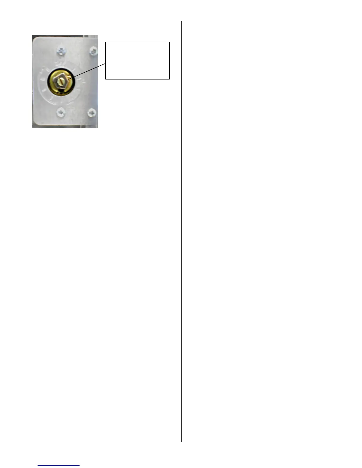
temperature again using one of the methods listed
above prior to further adjustment.
LOADING THE VENDER
All venders are shipped with an assortment of
spacers. Please contact a Service Representative or
refer to the proper Technical Publication for spacer
settings.
Load product in each column one package at a time
insuring that the package being loaded is in front of
the product pusher. If the package is narrower than
the column, use the correct spacer to insure a snug
(not tight) fit against the left side of the column. Test
the column spacing by pulling firmly on the front
package. If the package pulls out of the column
easily, recheck the spacer being used. Also insure
that the package is stable within the column (doesn’t
move excessively from side to side). Some packages
are wider at the base than in the center. These
packages will have the tendency to lean forward on
the front of the gate assembly and create a jam if not
properly set up. A properly loaded column will allow
the product to slide freely into the gate area but not
allow the product to squeeze past the front knuckle of
the release mechanism. After loading the vender, test
vend each column to insure proper operation.
LOADING CHANGE TUBES
The changer tubes can be loaded using one of the
following methods:
1. Load the coin mechanism with coins to the
desired level by inserting coins in the loading
slots on the coin tube front.
Minimum coin tube levels are:
6-8 nickels
7-8 dimes
5-6 quarters
Note: A low coin level in the coin tubes will
interfere with operation of the bill validator.
2. For exact cash accountability and to insure
maximum dollar bill acceptance, load the
mechanism utilizing the coin insert slot on the
front of the vender while in the coin tube
fill/dispense mode in the test menu. (see
page 17 in the programming section for more
information)
(For additional information about coin mechanism,
refer to the manufacturer’s instructions.)
POWER DISTRIBUTION BOX
The power distribution box is where the 120VAC input
voltage is broken down to the main operating voltages
of the vender (24 VAC and 12 VAC) by a transformer.
Those voltages are sent to the controller via the JI (12
pin) connector. It also contains 3 fuses that protect
the VMC, transformer, and solenoids. The power
distribution box also distributes AC power to the lights,
evaporator fan, and refrigeration system, which are
always energized when the vender is powered up. It
is located inside the service area, mounted to the
back wall.
VENDING MACHINE CONTROLLER (VMC)
The vending machine controller is the heart of the
Glass Front Vender and is located on the right side
wall inside the service area. It contains the program
chip (EPROM), which controls all aspects of the
vender with the exception of the refrigeration unit and
lighting. It also contains the power supply which
regulates the voltages required to operate the vend
solenoids as well as the changer, coin mechanism,
digital display and all logic functions in the vender.
Keypad
The keypad is located on the front of the service door.
It consists of a 6 inch X 3 inch matrix, membrane
switch pad and a rubberized actuator pad. The pad
utilizes the letters A thru F on the left side and
numbers 1 thru 0 along with the * symbol and Clr to
the right. The keypad is where the vender
programming is accomplished and where the
customers make their selections.
DIGITAL DISPLAY
The digital display is located directly above the
keypad on the front of the service door. It is an 8 digit
14-segment alphanumeric display. It is used to
convey information to the consumer as well as to the
person programming the vender. The backside of the
digital display, inside the service door, contains the
service mode switch. It is a blue button that is
depressed a number of times in order to access
different programming menus.
REFRIGERATION SYSTEM
The refrigeration system is a single piece unit and is
hermetically sealed. In the DN55##/DN35##/DN2145
models consist of a ½ horsepower compressor, with a
single fin and tube style condensing unit with one fan,
the condensation overflow pan and the evaporator.
The evaporator is located behind the panel on the
right side of the cooling compartment directly adjacent
to the bottom shelf. The remainder of the unit is
located behind the delivery bin, mounted to the bottom
Fig 1
Temperature Control
Adjustment. (Arrow
shows location of



 To Next Page