Digital Monitoring Products, Inc | 7000 Series Installation and Programming Guide 12
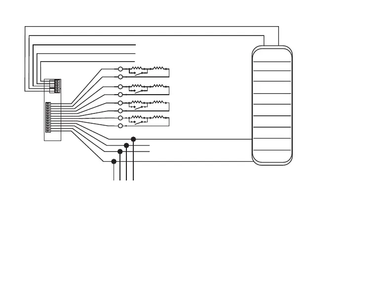
Figure 6: Access Control Wiring
Green/White* - Connect Reader Data 0
White - Connect Reader Data 1
Orange - Door Strike Normally Open
Gray - Door Strike Common
Violet - Door Strike Normally Closed
Black – Ground
Green – Receive Data
Yellow – Send Data
Red – Keypad Power
– Yellow & White
Zone 4
– Orange & White
Zone 3
(REX)
– Red & White
Zone 2
– Brown & White
Zone 1
(7/0 Panic)
NC
C
NO
WHT
GRN
Z4 -
Z4 +
Z3 -
Z3 +
Z2 -
Z2 +
Z1 -
Z1 +
BLK
GRN
YEL
RED
External Card
Reader
To Panel Keypad Bus
1K EOL
s
s
1K EOL
s
s
1K EOL
s
s
1K EOL
s
s
*Only the green/white,
white, black, and red
wires connect to the
external card reader.
 Loading...