Do you have a question about the DMP Electronics XR550 International Series and is the answer not in the manual?
Details power input, transformer, standby battery, auxiliary, and bell output specifications.
Describes built-in network communication and Contact ID capabilities for receivers.
Details the eight 1k Ohm EOL/Dual EOL burglary zones and two 3.3k Ohm EOL powered zones.
Explains connecting up to 16 supervised keypads and expansion modules to the keypad bus.
Lists devices connectable to LX-Bus connections: expansion modules and graphic annunciators.
Describes two SPDT relay outputs and four open collector outputs for various functions.
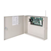
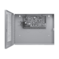
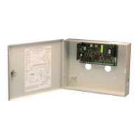
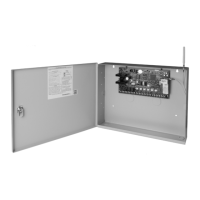
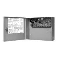
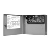
Details enclosure models, sizes, colors, and construction materials for the series.
Overview of the alarm panel system, including communicator, enclosure, battery, and keypads.
Details multiple options for zone expansion via keypads and LX-Bus connections.
Explains connecting output expansion modules to provide additional relays.
Describes panel programming for reporting to DMP receivers via various communication methods.
Highlights critical warnings about grounding, wiring, and potential equipment damage.
Provides instructions for applications conforming to standards and testing laboratories.
Diagram and description of accessory modules and their connections to the panel.
Details protection against voltage surges using MOVs and transient voltage suppressors.
Lists and describes various accessory cards, modules, keypads, and detectors.
Instructions for securely mounting the panel enclosure in a dry, secure location.
Guides for mounting DMP LCD keypads and zone expansion modules using backboxes.
Details wiring, performance factors, and limitations for LX-Bus/AX-Bus and keypad bus.
Steps to enable and associate wireless keypads with the panel using RF survey.
Instructions for connecting transformer wires to AC terminals 1 and 2.
Guidance on setting the 3-pin header for 75VA transformers for maximum amp output.
Details connecting battery leads to terminals 3 and 4, and using multiple batteries.
Explains optional connection to earth ground via terminal 4 for system operation.
Describes how to initiate a panel restart using battery power without AC.
Recommends replacing the battery every 3 to 5 years under normal usage.
Details battery charging float charge voltage and maximum current.
Explains how the panel tests battery voltage and detects low battery conditions.
Describes how the panel disconnects the battery to prevent deep discharge damage.
Provides a table for calculating panel and auxiliary device current draw for standby power.
Guides selecting battery type and quantity for 24, 60, or 72 hours of standby power.
Details supplying 12 VDC to alarm bells/horns and ground reference for the bell circuit.
Explains the keypad bus terminals and connecting up to 16 supervised keypads/modules.
Details terminal 7 supplying 12 VDC for keypads and auxiliary devices, shared current.
Describes terminal 8 receiving data from keypads and zone expansion modules.
Describes terminal 9 transmitting data to keypads and zone expansion modules.
Details terminal 10 as the ground reference for keypads and auxiliary devices.
Explains the 4-pin PROG header for connecting keypads for panel programming.
Describes LEDs indicating data transmission and receipt on the keypad bus.
Explains OVC LEDs indicating overcurrent on Keypad Bus and LX-Bus circuits.
Details terminal 11 for powering detectors and terminal 12 as ground reference.
Specifies current sharing for terminal 11 and total panel current draw limits.
Lists terminal connections for zones 1-8, their voltage sensing, and ground references.
Defines conditions (tamper, open, normal, short) and resistance/voltage parameters.
Specifies the delay for zone condition detection and fast response programming.
Enables arming and disarming selected areas using a keyswitch on an Arming type zone.
Details terminals 25-28 providing two resettable Class B, Style A, 2-wire powered zones.
Explains programmable SPDT relays for annunciation and control functions.
Specifies the 1 Amp at 30VDC rating for Model 305 relay contacts.
Details wiring and contact locations for accessing relay contacts via the 431 harness.
Explains programmable annunciator outputs that switch-to-ground for conditions.
Details wiring for open collector outputs using the 4-pin Model 300 harness.
Describes connecting the 860INT module for outputs 3-6 and electrical isolation.
Explains the XBUS header connection for the 1100XINT Wireless Receiver.
Describes LEDs indicating data transmission and receipt for the Wireless Bus.
Details LX-Bus headers, zone numbering, and AX-Bus compatibility for XR550INT.
Describes LEDs indicating data transmission and receipt for LX-Bus/AX-Bus connections.
Explains OVC LEDs for Keypad Bus, XBUS, LX500-LX700, and LX800-LX900 overcurrent.
Details the Ethernet connector for network connectivity and its specifications.
Describes Link and Activity LEDs indicating network connection status.
Recommends the Model 270 module for surge suppression on the Ethernet network.
Details connecting the panel to the telephone network using a DMP 356 RJ Cable.
Explains the built-in monitor for verifying telephone line voltage and connection.
Describes the RESET header for resetting the panel microprocessor and its procedure.
Explains the TAMPER header for supervising enclosure opening or removal.
Details the CELL MODULE header for connecting the DMP Model 263LTE-INT-A communicator.
Provides step-by-step instructions for installing the cellular module PCB.
Guides for connecting the antenna coax cable to the cell module and enclosure.
| Brand | DMP Electronics |
|---|---|
| Model | XR550 International Series |
| Category | Control Panel |
| Language | English |
