Do you have a question about the DMP Electronics XR2400F and is the answer not in the manual?
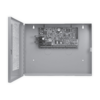
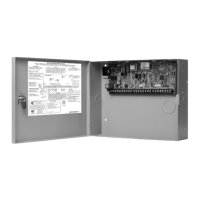
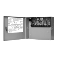
Provides a general overview of the XR2400F Addressable Fire Alarm Control Panel and its capabilities.
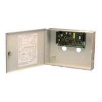
Lists the various components included in the XR2400F FACP system.
Details the power input, standby battery, auxiliary, and NAC output specifications for the panel.
Recommends reading the entire guide and understanding caution statements before installation.
Outlines the organization of the installation guide into five sections.
Guides the user on how to locate information within the manual.
Describes how to mount the XR2400F enclosure securely in a dry location.
Details the process for surface mounting the enclosure, emphasizing stud attachment.
Explains how to flush mount (recess) the enclosure between wall studs.
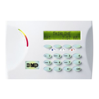
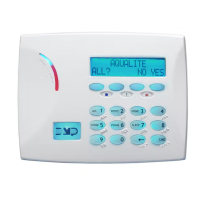
Describes the factory-installed Fire Command Center keyboard and its keyswitch functionality.
Illustrates the layout and connections of the XR2400F system components.
Details AC power connection, transformer wiring, and grounding requirements.
Explains the function and connection of the 28 VAC transformer.
Introduces the system's battery connection for 24 VDC operation.
Details how to connect a 12 VDC battery to the XR2400F panel.
Explains connecting 24 VDC batteries to the 504-24 Power Supply.
Describes the 866 module's function for supervising notification appliances.
Details the pre-installation and connection of the 866 modules.
Explains the operation of the bell silence switch and trouble contacts on the 866 module.
Describes the 462N card's function to add zones to the XR2400F.
Details the devices that can be connected via the LX-Bus™ and its capacity.
Provides step-by-step instructions for installing the 462N expansion card.
Explains how to connect the XR2400F to the public telephone network.
Provides the FCC registration number and ringer equivalence for the panel.
Lists requirements for notifying the telephone company about terminal equipment.
States that ground start phones cannot be used for fire applications.
Describes the 893A module's function for phone line supervision.
Details connecting the 893A module to the XR2400F panel and communication jumpers.
Explains how to set jumpers for DD or MPX configuration.
Describes configuring the 893A for digital dialer or multiplex operation.
Explains the phone line monitoring feature and its display of system trouble.
Details the 893A's monitoring of the panel's CPU and the processor fail buzzer.
Describes the 504-24 as a power supply meeting various compliance standards.
Explains the status LEDs on the 504-24 power supply.
Provides a chart detailing conditions and their corresponding LED status.
Lists the UL standards and specifications the 504-24 complies with.
Outlines the calculation process for required battery Amp.hours for the system.
States the 24 VDC power supply is pre-wired and refers to wiring diagrams.
Explains the colors and connections of wires on the interconnect wiring harness.
Describes the LCD display and keyboard for programming and operation.
Details the factory pre-wiring of the display and keyboard to the panel.
Mentions connecting up to seven remote Fire Command Centers.
Describes the XR2400F Command Processor as a versatile fire communicator panel.
Refers to wiring diagrams and subsequent sections for applications.
Explains the function of the two Model 305 relays for zone alarm control.
Identifies how NAC modules and the power supply are connected to zones.
Lists transformer input, standby battery, auxiliary, and bell output specs.
Details various communication methods supported by the panel.
Describes the types and number of zones available on the panel.
Mentions connecting supervised keypads or expanders to the data bus.
Lists devices that can be connected via the LX-Bus.
Describes the SPDT relay outputs and their ratings.
Explains how to add additional zones using keypads and expander modules.
Details expanding output capabilities with Model 716 Output Expanders and Model 717.
Shows wiring for various accessory modules like transformers, power supplies, and keypads.
Discusses protection against voltage surges using MOV and TVS suppressors.
Lists and describes various interface adaptors, expansion modules, and indicating devices.
Provides instructions for mounting keypads and zone expander modules.
Discusses keypad data bus and LX-Bus wiring distances and capacities.
Explains the procedure for restarting the panel without AC power.
Recommends replacing batteries every 3 to 5 years.
Details battery charging voltage and current specifications.
Explains the panel's battery testing and low battery detection process.
Describes the panel's battery cutoff feature to prevent deep discharge.
Lists power requirements for the panel and auxiliary devices for battery calculations.
Describes the 12 VDC bell output and ground reference.
Explains terminals used for keypad data bus and connecting devices.
Details terminal 7 for 12 VDC power to expanders and its current limit.
Identifies terminal 8 for data receive.
Identifies terminal 9 for data transmit.
Identifies terminal 10 as the ground reference for the bus.
Describes the 12 VDC output for smoke detectors and its ground reference.
States the current rating for terminal 11 and its shared capacity.
Explains the two resettable Class B powered zones for 2-wire smoke detectors.
Describes the grounded burglary zones and their terminal connections.
Lists resistance and voltage parameters for zone conditions (open, normal, short).
Details the 500ms detection time and fast response option for zones.
Explains using a keyswitch on an arming zone for simplified arm/disarm.
Describes the two SPDT relays for zone alarm control and functions.
Specifies the 1 Amp at 30 VDC resistive rating for relay contacts.
Shows contact locations on the DMP 430 Output Harness for relays.
Details eight 12 VDC, 50mA resistive voltage outputs for powering devices.
Shows output locations on the DMP 430 Harness for voltage outputs.
Explains the use of the J16 header to reset the microprocessor.
Details the J4 header for tamper switch wiring and supervision.
States programming and installation specs for UL burglary standards.
Specifies wiring compliance with NEC, ANSI/NFPA 70, UL 681, and UL 611.
Recommends using specific devices for panels installed outside protected areas.
Notes restrictions on programming police station phone numbers.
Requires Bypass Reports to be programmed as YES for UL burglary applications.
Emphasizes proper installation, maintenance, and testing.
Details partition usage for UL burglary applications and tamper protection.
Lists verified DMP and other receivers for operation.
Specifies the minimum Bell Cutoff time.
Sets the maximum entry delay time.
Sets the maximum exit delay time.
States that the product should be tested weekly.
Defines the maximum number of panels for MPX/DNET receiving lines.
Requires Opening/Closing Reports to be programmed as YES.
Requires the Closing Wait option to be programmed YES.
States the panel provides Grade A proprietary service as a dialer.
Details HST network communication requirements and AA Central Station Service.
Requires a keypad to display system monitor troubles.
Specifies that dialer numbers must begin with D or P.
Sets the maximum entry delay to 60 seconds.
Sets the maximum exit delay to 60 seconds.
Programs the XR2400F to send a report once every 24 hours.
Requires the Closing Wait option to be programmed YES.
Requires a keypad to display system monitor troubles.
Mandates the use of a Grade A local audible signal appliance.
Specifies the minimum Bell Cutoff time to 15 minutes.
Requires the Automatic Bell Test option to be programmed as YES.
Basic line security for Police Connect when configured as a dialer system.
High Line Security for MPX, DNET, or HST systems, including dialer supervision.
States programming and installation specs for UL or NFPA fire standards.
Specifies wiring compliance with NEC, ANSI/NFPA 70.
Recommends Model 320 wire-in transformer mounted within 20 feet by conduit.
Specifies Model 310 1k Ohm EOL resistor for 1k Ohm EOL fire zones.
Requires a keypad to display system monitor troubles.
Requires a keypad to display fire troubles and alarms.
Notes restrictions on programming police station phone numbers.
Emphasizes proper installation, maintenance, and testing.
Recommends programming Fire Type zones for audible alarms.
Details retard delay limits for waterflow zones and exclusion for smoke detectors.
Mentions DMP 869 Dual Style D Module for two Style D zones.
Recommends selecting Video Option as NO when fire protection is connected.
Lists verified DMP and other receivers for operation.
Defines programming for steady burglary alarms and pulsed/temporal fire alarms.
Requires Restoral Reports option to be YES or DISARM.
Sets the Power Fail Delay option to 6 hours.
Details programming for sprinkler supervisory zones and module usage.
Requires two phone lines for DACT systems and module usage.
Explains providing service via MPX communication to SCS-1 receiver.
Details providing service via MPX and digital dialer backup.
Discusses module usage for bell circuits and keypad display of troubles.
Defines programming for steady burglary alarms and pulsed/temporal fire alarms.
Shows wiring for multiple 866 indicating circuit modules.
Illustrates wiring for zoned annunciation using multiple 866 modules.
Shows wiring for the Model 869 Dual Style D Initiating Module.
Illustrates wiring for connecting Radionics Model D127 Reversing Relay Modules.
Shows wiring for a supervised remote DPDT relay using Model 866.
Illustrates the wiring for cellular backup communication.
Shows wiring for LX-Bus expansion cards and modules like notification circuits.
Illustrates wiring for a second LX-Bus with an auxiliary power supply.
Describes the display behavior during normal standby.
Describes the display behavior during an alarm condition.
Explains the keyswitch function for enabling operation keys.
Details how to silence alarms without cancelling central station reports.
Provides steps to reset smoke or other detectors via the user menu.
Describes how trouble conditions are displayed and how to silence them.
Explains how to test the security system's operation and communication.
Provides contact information for service if required.
| Brand | DMP Electronics |
|---|---|
| Model | XR2400F |
| Category | Control Panel |
| Language | English |
