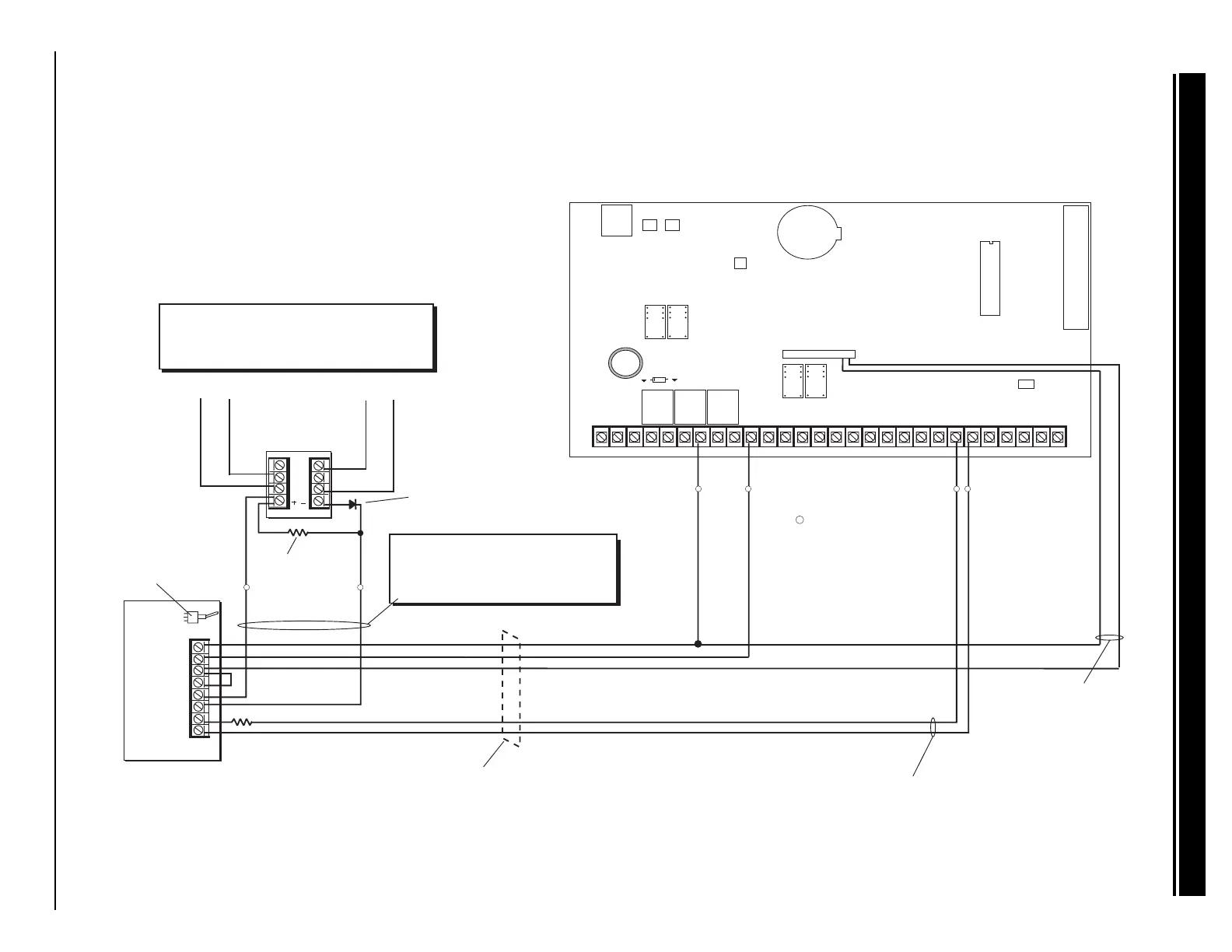
System Wiring Diagrams
XR2400F Installation Guide
2500 N. Partnership Boulevard Springfield, MO 65803 www.dmpnet.com Digital Monitoring Products
37
1
2
3
4
5
6
7
8
Auxiliary Power
Ground
Alarm Input
Bell Power Input
Bell Output +
Bell Output -
Bell Trouble
Bell Trouble
DMP part #DI-0001 Rectifier
(1N4001 diode) in series with
input from Model 866 terminal 6.
10k Ω EOL Resistor
DMP Model 308
Indicating Circuit Module
DMP Model 866
37mA at 12 VDC
1k Ω
Normally Open
contacts will close
on alarm.
Normally Closed
contacts will open
on alarm.
DPDT Relay
Use Model ASRB-1 from Advanced Signaling.
30mA coil operating current at 12 VDC.
Model 430
Output Harness
Relay #1 N/O (Orange)
Remote DPDT
Relay
Supervised
Silence switch
Wiring between the 866 module and the
DPDT relay is supervised against opens,
shorts, and grounds. Either of these
trouble conditions cause the 866 module's
Bell Trouble contacts to open.
The zone connected to the Bell Trouble contacts on the 866 Indicating
Circuit Module must be programmed as a Supervisory Type zone and
selected for display in the keypad status list.
The 866 module must be installed in the
panel enclosure or in a 340FC, 349, or 350
enclosure connected by conduit.
J4
J16
Command Processor Reset
Output Header J2
All outputs must be connected
to devices located within the
same room as the control panel.
K4
J11J12
DD, MPX
Selection
Tamper Header
AC
1
234
56
78
10 11 12
13
14
15
16
17
18
19
AC +B -B
BELL
GND
SMK
GND
9
RED
YEL GRN BLK
20
21
22 23 24 25
26
27 28
Z1 Z2
GND
GND
GND
GND
Z3
Z4 Z5 Z6 Z7 Z8 Z9- Z9+ Z10- Z10+
Answering Machine
Bypass Relay
Use Model 305
K2
Phone Jack Connector
J3
Lithium Battery
K7
K6
Relay Output 1
Use Model 305
Relay Output 2
Use Model 305
J6
J2
Relay #1 Common (Gray)
= Supervised Circuit
S
S S SS
S S
34.5 Supervised remote relay