6
Installation
XR2400F Installation Guide
Digital Monitoring Products www.dmpnet.com 2500 N. Partnership Boulevard Springfield, MO 65803
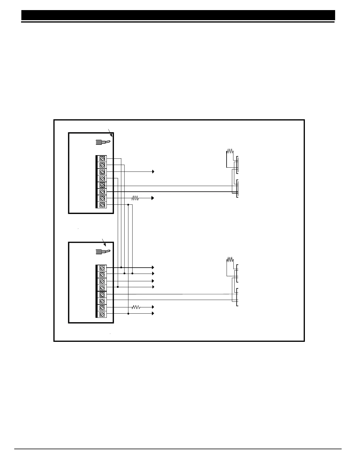
Two 866 NAC Modules
5.1 Description
Each 866 provides one style W indicating circuit for supervising UL polarized notification appliances, such as
bells, strobes, and horns. See Table 1: Notification Appliances for a list of approved notification appliances.
5.2 Connection
Each 866 module is pre-installed on the right side of the enclosure wall using the standard three-hole
configuration. The modules are factory pre-wired to each other, the 504-24, and the XR2400F panel. Refer to
figure below and to Figure 2: XR2400F System for wiring connections.
You can connect 24 VDC Notification Appliances to terminals 5 and 6 of each module. Each module provides a
zone of notification and can be activated separately.
Figure 5: 866 Wiring Diagram
5.3 Bell Silence/Bell Trouble
A bell silence switch on the 866 module is provided to prevent sounding of the indicating devices when testing
the system. When the Silence position is selected, a fifteen second delay occurs before the 866 bell trouble
contacts (terminals 7 and 8) open. Select the Normal position after testing to return the 866 module to normal
operation.
10K
DMP
To XR2400F 0utput #1 (J2 pin #2)
Pre-installed 1K EOLR
To XR2400F terminal 13 ( Zone 1)
To XR2400F terminal 7
To 504-24 DC (-)
To XR2400F output #2 (J2 pin #5)
To 504-24 DC (+)
To XR2400F terminal 15 ( Zone 2)
To 504-24 BATT TRBL C (Common)
866
Module #1
866
Module #2
Normal/Silence Switch
Normal/Silence Switch
1 AUX PWR
2 GND
3 Alarm In
4 B ell PW R In
5 Bell Out +
6 Bell Out -
7 Bell Trouble
8 Bell Trouble
1 AUX PWR
2 GND
3 Alarm In
4 Bell PWR In
5 Bell Out +
6 Bell Out -
7 Bell Trouble
8 Bell Trouble
Pre-installed 1K EOLR
10K
DMP