3
Installation
XR2400F Installation
Guide
2500 N. Partnership Boulevard Springfield, MO 65803 www.dmpnet.com Digital Monitoring Products
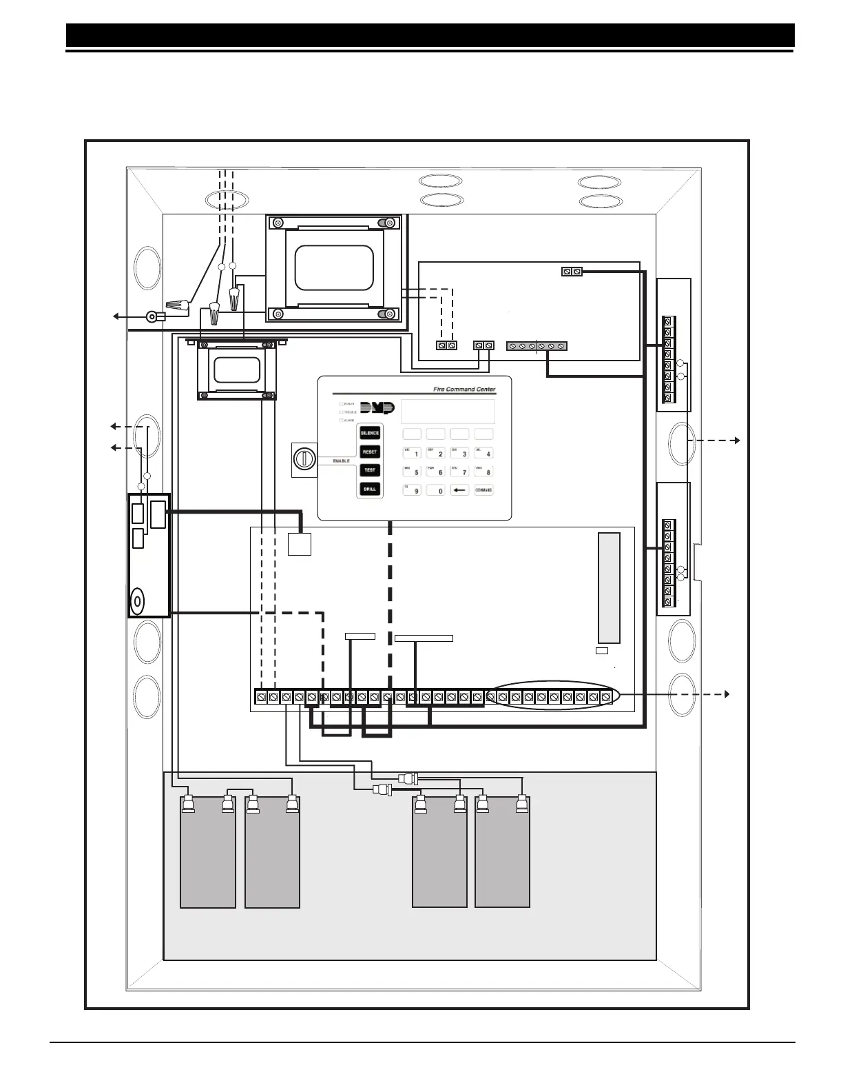
2.5 Wiring diagram
The XR2400F system below shows the layout of the components. The wires shown in this guide have been
factory installed and connected. The dashed lines represent wires that run underneath a component. Detailed
wiring diagrams for each supplied component appear in following sections of this guide.
Figure 2: XR2400F System
866
Module
#2
866
Module
#1
28 VAC Transformer
WHITE
BLACK
BLACK
GREEN
WHITE
16.5 VAC
Transformer
J16
Reset
Output Header J2
AC
123
4
5
6
7
8
10
11
12 13 14 15 16 17 18
19
9
20
21 22
23
24 25 26
27 28
AC +B
-B
BELL
GND SMK GNDRED
YEL
GRN BLK Z1 Z2GND
GND GND GND
Z3 Z4 Z5 Z6
Z7
Z8 Z9 +
Z9 -
Z10 + Z10 -
J3
J10
AC AC
+ BAT -
NC C NO NC C NO
AC TRBL BATT TRBL
+ DC DC
-
Black wire to negative
battery terminal
Red wire to positive
battery terminal
To 24 VDC
battery
504-24 Power Supply
893A
Install batteries as shown above.
XR2400F Command
Processor Panel
To Telco
S
S
To Notification
Appliances
To Notification
Appliances
462 N LX-Bus Zone Expansion
Card
+
-
+
-
+
-
+
-
Two 12 VDC batteries connected
in parallel with a Model 318 Dual
Battery Harness. See
Secondary Power Supply
section.
12 VDC
battery
12 VDC
battery
Two 12 VDC batteries connected
with a Series Connecting Strap.
Total of 24 VDC for 504-24
Power Supply. See Secondary
Power Supply section.
12 VDC
battery
12 VDC
battery
From 504-24 Power
Supply to 24 VDC.
From XR2400F
panel to 12 VDC.
Keyswitch
Red
Black
Black
Red
Bonding
Strap to
Door
S
S
S
S
S
S
Power limited/class 2-wire routing
through conduit knockouts
Power limited/class 2-wire
routing through conduit
knockouts
Power limited/class
2-wire routing
through conduit
knockouts