12
Installation
XR2400F Installation Guide
Digital Monitoring Products www.dmpnet.com 2500 N. Partnership Boulevard Springfield, MO 65803
Interconnect Wiring Harness
10.1 Interconnect Harness
This chart explains the colors of the wires on the Interconnect Wiring Harnesses. It also explains what each
wire connects.
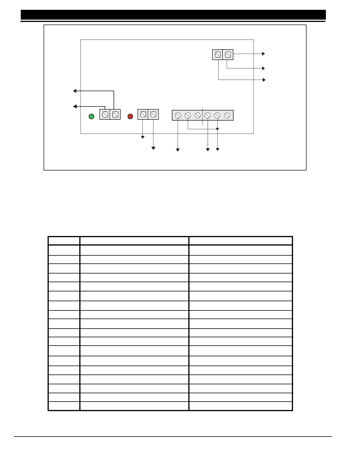
Figure 9: 504-24 Wiring Diagram
Table 4: Interconnect Wiring Harness
AC TRBL BATT TRBL
To 866 Module
#2 terminal 4
(Bell PWR In)
Black wire to negative
battery terminal
Red wire to positive
battery terminal
To 24 VDC
battery
Both wires
To 28 VAC
Transformer
To 866 Module
#2 terminal 8
(BELL TRBL)
To XR200 Panel
terminal 16
(Zone 3)
To XR200 Panel
terminal 10 (BLK)
AC
DC
Green
LED
Red
LED
White/Red
Black
Black
Green
Black
Yellow
Blue
To 866 Module #2
terminal 2 (GND)
Model 504-24 Power Supply
+ DC DC-
AC AC
+ BAT -
To XR200 Panel
terminal 18
(Zone 4)
NC C NO NC C NO
Color From To
Red Panel terminal 7 (DC Power) 866 Module #2 terminal 1 (AUX PWR)
Black Panel terminal 10 (Common) 504-24 DC-
Brown Panel terminal 13 (Zone 1) 866 Module #1 terminal 7 (Bell Trouble)
Violet Panel terminal 15 (Zone 2) 866 Module #2 terminal 7 (Bell Trouble)
Green Panel terminal 16 (Zone 3) 504-24 Battery Trouble terminal N/O
White Panel terminal 18 (Zone 4) 504-24 AC Trouble terminal N/C
Blue Panel J2 pin 2 (Common) 866 Module #1 terminal 3 (Alarm In)
Orange Panel J2 pin 3 (Output 1 N/O) Panel terminal 5 (Bell Output)
Yellow Panel J2 pin 5 (Common) 866 Module #2 terminal 3 (Alarm In)
Orange Panel J2 pin 6 (Output 2 N/O) Panel terminal 5 (Bell Output)
White/Red 504-24 DC+ 866 Module #2 terminal 4 (Bell PWR In)
Black 504-24 DC- 866 Module #2 terminal 2 (GND)
Red 866 Module #2 terminal 1 (AUX PWR) 866 Module #1 terminal 1 (AUX PWR)
Black 866 Module #2 terminal 2 (GND) 866 Module #1 terminal 2 (GND)
Black 866 Module #2 terminal 2 (GND) 866 Module #1 terminal 8 (Bell Trouble)
White/Red 866 Module #2 terminal 4 (Bell PWR In) 866 module #1 terminal 4 (Bell PWR In)
Black 866 Module #2 terminal 8 (Bell Trouble) 504-24 Battery Trouble terminal Common
Black 866 Module #2 terminal 8 (Bell Trouble) 866 Module #1 terminal 8 (Bell Trouble)