System Wiring Diagrams
40
XR2400F Installation Guide
Digital Monitoring Products www.dmpnet.com 2500 N. Partnership Boulevard Springfield, MO 65803
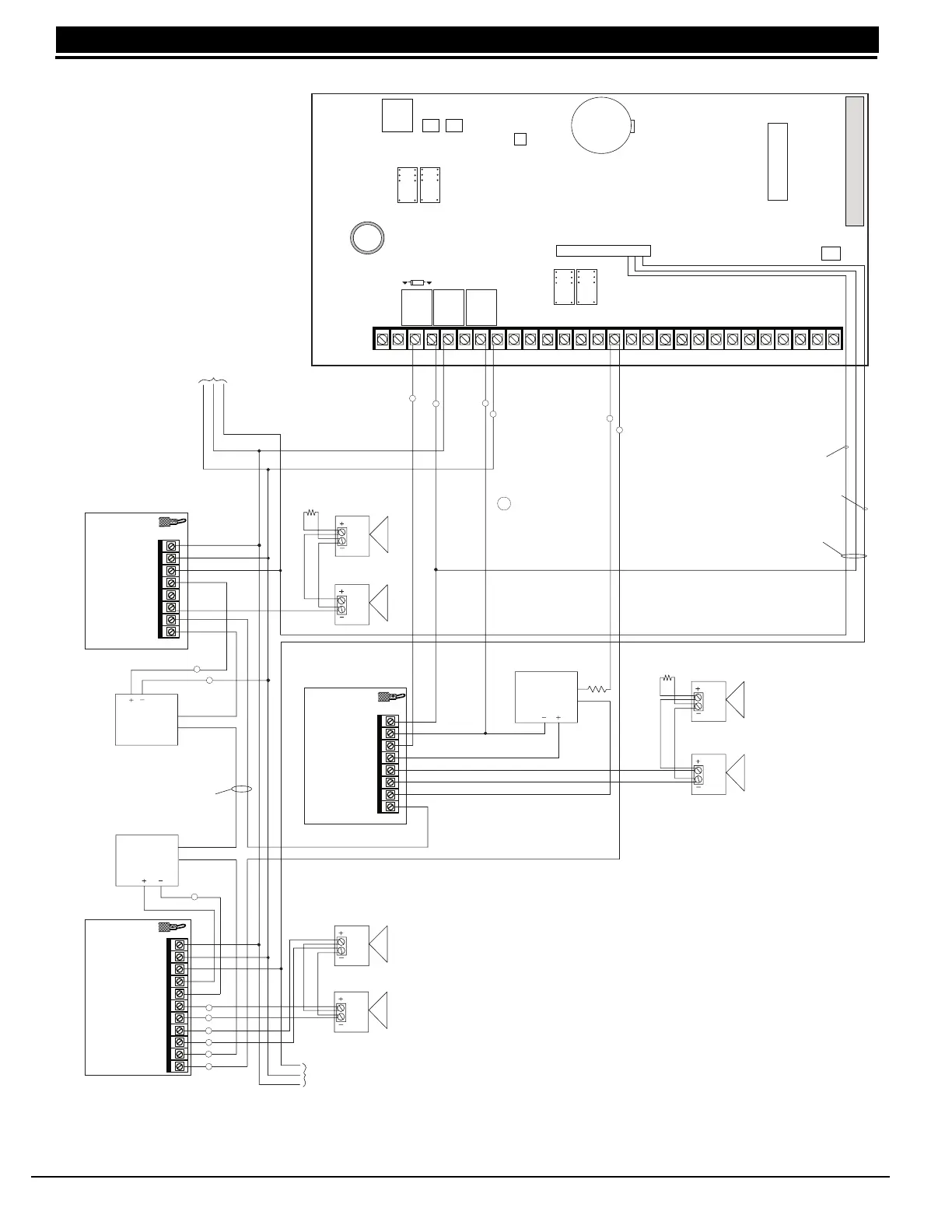
34.8 Second LX-Bus with Auxiliary Power Supply
1 Auxiliary Power
3 Alarm Input
4 Bell Power Input +
6 Bell A Output +
7 Bell A Output -
10 Bell Trouble
2 Ground
11 Bell Trouble
5 Bell Power Input -
8 Bell A Output +
9 Bell A Output -
1 Auxiliary Power
3 Alarm Input
4 Bell Power Input
5 Bell Output +
6 Bell Output -
7 Bell Trouble
2 Ground
8 Bell Trouble
Phone Jack
Connector
J3
J11J12
DD, MPX
Selection
AC AC +B -B BELL GND SMK GNDRED YEL GRN BLK Z1 Z2GND GND GND GNDZ3 Z4 Z5 Z6 Z7 Z8 Z9 + Z9 - Z10 + Z10 -
J4
J16
Tamper Header
12345678
10 11 12 13 14 15 16 17 18 19
9
20 21 22 23 24 25 26 27 28
J6 Interface Connector
J6
K4
K2
Battery Only Restart CR7
Ground Start Relay
Use Model 305
Answering Machine
Bypass Relay
Use Model 305
Lithium Battery
K7
K6
Relay Output 1
Use Model 305
Relay Output 2
Use Model 305
EPROM Socket
Output Header J2
24 VDC 5 Amp
Maximum
Power Supply Trouble
Contacts N/C
Auxiliary power supplies must
be regulated UL listed for Fire
Protection Signaling Service.
Power supplies must have bat-
tery backup.
UL Listed, Polarized
Indicating Devices
Style Y
10k Ω EOL Resistor
DMP Model 308
You can have up to twenty-five 866
Indicating Circuit Modules by using
the relay outputs available on the
XR2400F panel.
All modules must be installed within
a 340FC, 349, or 350 enclosure
connected by no more than 20 feet of
conduit.
Zone 1 Indicating Circuit
Module. DMP Model 866
45mA at 12 VDC
To additional Zone 1
Indicating Circuit
Modules.
To additional Zone 2
Indicating circuit
modules
Zone 1
Output
Zone 2
Output
Outputs 3 to 10 can
switch up to 50mA
each at 12 VDC. This is
sufficient for one 866
module per indicating
zone 3 to 10.
Relay 1
N/O
Orange
Relays 1 and 2
Common
Gray
Model 430
Output Harness
1k Ω
Style W
Style W
S
= Supervised Circuit
S
S
S
S
S
S
504-24
Power
Supply
24 VDC 5 Amp
Maximum
504-24
Power
Supply
S
1 Auxiliary Power
3 Alarm Input
4 Bell Power Input
5 Bell Output +
6 Bell Output -
7 Bell Trouble
2 Ground
8 Bell Trouble
Common
Indicating Circuit
Module DMP Model
866 45mA at 12 VDC
S
S
S
S
S
S
24 VDC 5 Amp
Maximum
504-24
Power
Supply
10k Ω EOL Resistor
DMP Model 308
S
S
Relay 2
N/O
Orange
The Auxiliary Power Supply and Indicating
Circuit Module trouble contact zone must be
programmed as a Supervisory Type Zone
and must be selected for display in the
keypad status list. See the XR200 and
XR2400F Programming Guide (LT-0196).
NOTE: If an auxiliary supply is not used,
terminals 3 and 4 on the 866 Indicating
Circuit Module can be jumpered together to
supply bell power from the XR2400F panel.
A Maximum of 1.5 Amps at 12 VDC is
available from terminal 5 of the
XR2400F
Zone 2 Indicating Circuit
Module. DMP Model 865
26mA at 12 VDC