14
Installation
XR2400F Installation Guide
Digital Monitoring Products www.dmpnet.com 2500 N. Partnership Boulevard Springfield, MO 65803
J4
J16
Command
Processor
Reset
Output Header J2
J11J12
DD, MPX
Selection
Tamper Header
AC
12345678
10 11 12 13 14 15 16 17 18 1
9
9
20 21 22 23 24 25 26 27 28
AC +B -B BELL GND SMK GNDRED YEL GRN BLK Z1 Z2GND GND GND GNDZ3 Z4 Z5 Z6 Z7 Z8 Z9 + Z9 - Z10 + Z10 -
Phone Jack Connector
J3
Relay Output 1
462 N Network Interface Card
J6
Form C Relays
Output 1 N/C Violet
Output 1 Com Gray
Output 1 N/O Orange
Output 2 N/C Violet
Output 2 Com Gray
Output 2 N/O Orange
Voltage Outputs
Output 3 White/Orange
Output 4 White/Yellow
Output 5 White/Green
Output 6 White/Blue
Output 7 White/Violet
Output 8 White/Gray
Output 9 White
Output 10 White/Black
Ground Black
J2 Output color code for
Model 430 Output Harness
To 16.5 VAC
transformer
To 866 Module
#1, terminal 7
(Bell Trouble)
To 893A J3 connector
To 866 Module
#1 terminal 3
(Alarm In)
To 866 Module
#2 terminal 3
(Alarm In)
J10
To 893A P10
Connector
To 504-24
BATT
TRBL NC
Black wire to negative
terminal of 12 VDC
battery
To 866 Module # 2,
terminal 1(AUX
PWR)
To Fire Command
Center
To 504-24
DC -
Red wire to positive
terminal of 12 VDC
battery
To LX-Bus
Modules
To 504-24
AC TRBL
NC
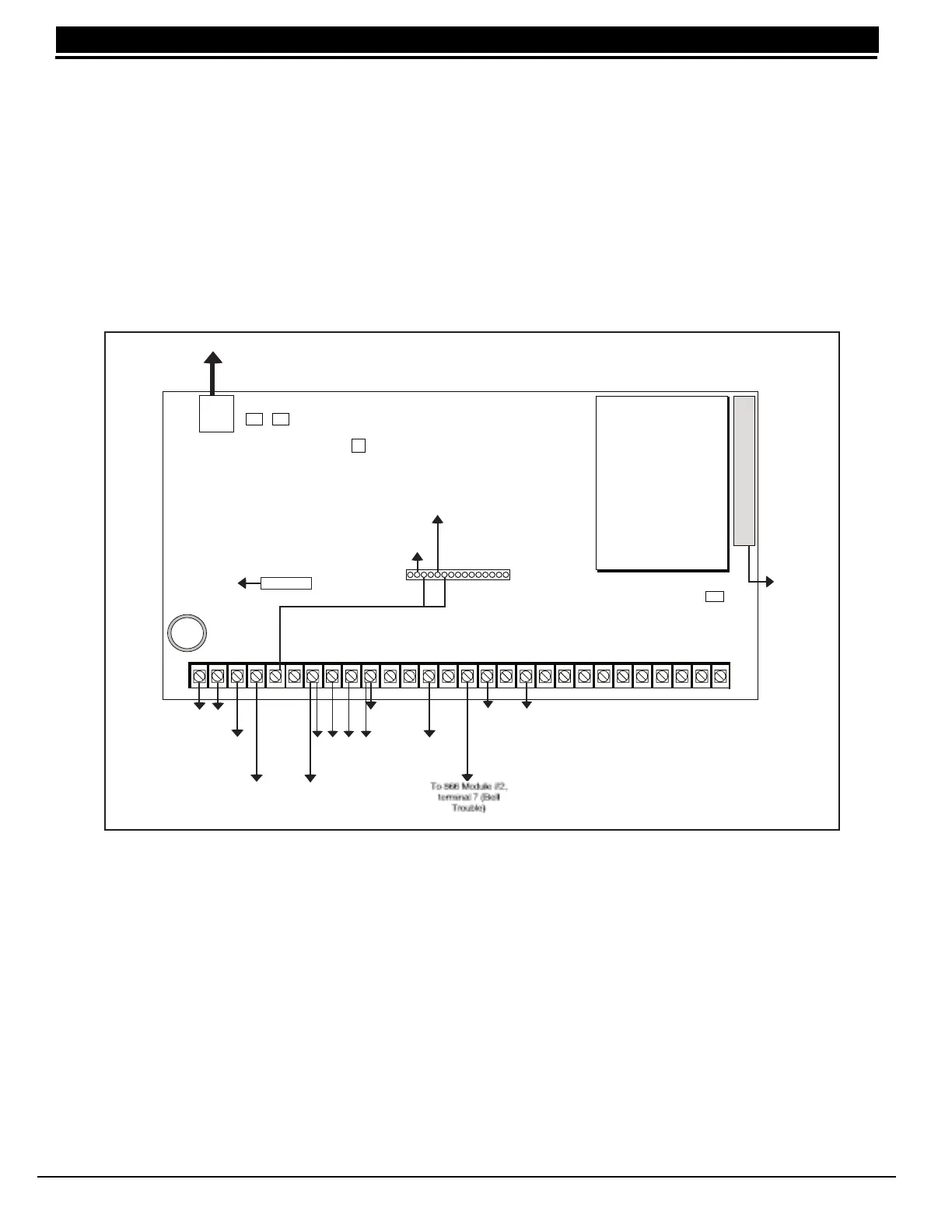
XR2400F Command Processor Panel
12.1 Description
The DMP XR2400F Command Processor is a versatile fire communicator panel with battery backup. The
XR2400F provides eight on-board grounded zones for connection of Model 869 class A zones and two on-board
12 VDC class B style A powered zones. The powered zones have a reset capability to provide for 2-wire smoke
detectors, relays, or other latching devices. The XR2400F can communicate to one or two DMP SCS-1
Receivers using multiplex or digital dialer, or to non-DMP receivers using the Contact ID and Modem IIe formats.
12.2 Connection
The XR2400F Command Processor panel is factory pre-wired and controls the other components in the system.
Refer to the wiring diagram below for wiring. See the following sections for descriptions of additional
applications of the XR2400F.
Figure 11: XR2400F Panel Wiring Diagram
12.3 Relays
The XR2400F is shipped with two Model 305 Relays pre-installed to allow zone alarm control for the 866 NAC
Modules. When a fire alarm occurs the bell output is factory programmed to turn on and provide power to the
contacts of the relays. Specific zone programming determines whether one or both relays turn on signal voltage
to the 866 NACs. This allows control of the NACs by zone.
12.4 Zone Reference
The XR2400F has been pre-wired in the factory. The first 866 NAC module connects to Zone 1. The second
866 NAC module connects to Zone 2. Zone 3 is connected to the 504-24 power supply.