17
Installation
XR2400F Installation Guide
2500 N. Partnership Boulevard Springfield, MO 65803 www.dmpnet.com Digital Monitoring Products
Accessory Devices
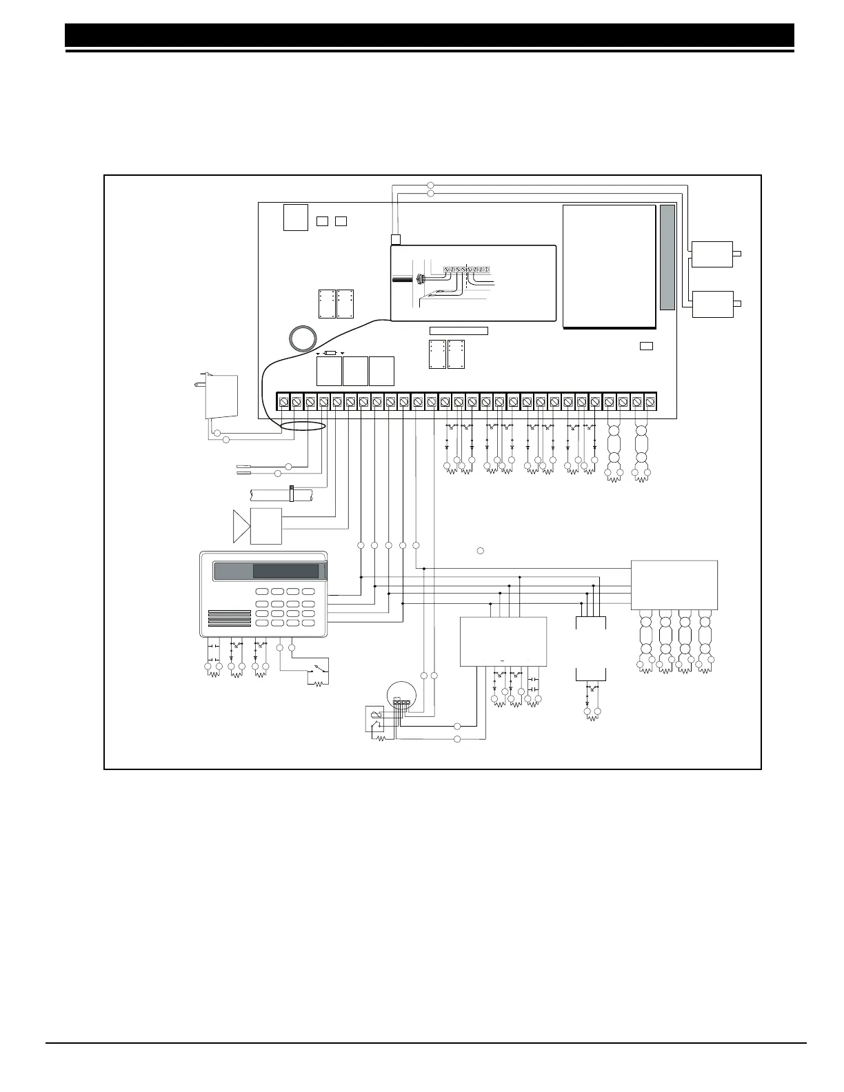
15.1 Wiring diagram
The XR2400F system below shows some of the accessory modules you can connect for use in various
applications. A brief description of each module appears in section Accessory Devices.
15.2 Lightning protection
Metal Oxide Varistors and Transient Voltage Suppressors help protect against voltage surges on input and
output circuits of the XR2400F. Additional surge protection is available by installing the DMP 370 or 370RJ
Lightning Suppressors.
Figure 13: Typical XR2400F Wiring diagram
Resistor
DMP Model 309
J4
Battery Only Restart CR7
J16
Command
Processor
Reset
ZONE EXPANDER
Model 714
15mAat 12 VDC
Models 714-8, 714-16
20mA @ 12 VDC
RED
BLACK
22 GA. MIN
GREEN
22 GA. MIN
BLACK
22 GA. MIN
YELLOW
22 GA. MIN
RED
Cold Water Pipe
Earth Ground
Yellow
Red
Green
Black
16 to 18 gauge wire
+
Ð
DMP Model 310
Smoke
Detector
Power
Supervision
Relay
Output Header J2
K4
J11J12
Ground Start Relay
Use Model 305
DD, MPX
Selection
Rear Tamper
Front Tamper
Tamper Header
ZONE 5
ZONE 1
ZONE 2
ZONE 3
ZONE 4
AC
1 2 3 4 5 6 7 8 10 11 12 13 14 15 16 17 18 1
9
9 20 21 22 23 24 25 26 27 28
AC +B -B BELL GND SMK GNDRED YEL GRN BLK Z1 Z2GND GND GND GNDZ3 Z4 Z5 Z6 Z7 Z8 Z9 + Z9 - Z10 + Z10 -
1k
Ω
ZONE 6
ZONE 7
ZONE 8
3.3k Ω
Resistor
DMP Model 309
K2
Phone Jack Connector
J3
K7K6
Relay Output 1
Use Model 305
Relay Output 2
Use Model 305
J6 Interface Connector
J6
J2
ZONE 9
ZONE 10
Red
Form C Relays
Output 1 N/C Violet
Output 1 Com Gray
Output 1 N/O Orange
Output 2 N/C Violet
Output 2 Com Gray
Output 2 N/O Orange
Voltage Outputs
Output 3 White/Orange
Output 4 White/Yellow
Output 5 White/Green
Output 6 White/Blue
Output 7 White/Violet
Output 8 White/Gray
Output 9 White
Output 10 White/Black
Ground Black
J2 Output color code for
Model 430 Output Harness
ARM
DISARM
1k
Ω
Auxiliary Power
Total current 1.0 Amps
combined from Terminals
7, 11, 26, & 28.
ZONE EXPANDER
Model 715
25mA @ 12 VDC
Models 715-8, 715-16
20mA @ 12 VDC
ZONE
EXPANDER
Model 711/711E
12mA at
12 VDC
Wiring on terminals
5 through 22 must
exit to the right and
maintain a 1/4"
separation from the
AC and battery
positive wiring.
= Supervised Circuit
Heat detectors, pull
stations, or any
other contact devic-
es listed for Fire
Protective Signaling
can be connected to
zones 9 and 10.
Keypads
Model 670, 770, and 771
125mA at 8 to 16 VDC.
Model 690
90mA at 8 to 16 VDC.
Model 790 and 791
100mA at 8 to 16 VDC.
Model 793
130 mA at 8 to 16 VDC.
Maximum AC wire distance
With 16 gauge wire: 70 feet
With 18 guage wire: 40 feet
DMP transformers:
Model 320
16.5 VAC 40VA
Class 2 wire-in.
Model 321
16.5 VAC 40VA
Class 2 plug-in.
Model 322
16.5 VAC 100VA
Class 2 wire-in.
Bell
12 VDC nominal
Total current 1.5 Amps
max.
Minimum cutoff time is 5
minutes.
Plug into
120 VAC
60Hz outlet
not con-
trolled by
switch.
Keyswitch Arming
Can be connected to any loop.
See section 13.4.
Secondary Power Supply
1.2 Amps max. charging current.
Use only 12 VDC rechargable
batteries. DMP Model 367.
Replace every 3 to 5 years.
Refer to LT-0164 for a list of approved 4-wire
smoke detectors and power supervision relays.
Tamper protection
when required for
Model 350A Attack
Resistant Enclosure.
Answering
Machine
Bypass Relay
Use Model 305
AC wiring must be in conduit and exit out the left
side of the enclosure.
Bell
1k
Ω
1k
Ω
1k
Ω
1k
Ω
1k
Ω
1k
Ω
1k
Ω
1k
Ω
1k
Ω
1k
Ω
1k
Ω
1k
Ω
1k
Ω
1k
Ω
3.3k Ω
3.3k Ω 3.3k Ω 3.3k Ω 3.3k Ω
s
s s s s s
s
s
s
s
s
s
s s s s s s
s s
s s
s
s
s s
sss
s
s
s
s
s
s
s
s
s
s
s
ssss
s
sss
ss
s
ss
s
s
s
s
ss
s
Zones 9 and 10 and
Model 715 compatibility
identifier: A
Maximum operating
range:
8.8 VDC to 14.2 VDC.
Class B (Style A).
1k
Ω
Keypads
Model 670, 770, and 771
125mA at 8 to 16 VDC.
Model 690
100mA at 8 to 16 VDC.
Model 790, 791, and 793
100mA at 8 to 16 VDC.
Zone Expander
Model 714
7mA @ 12 VDC
Model 714-8, 714-16
20mA @ 12 VDC
Zone Expander
Model 715
7mA @ 12 VDC
Model 715-8, 715-16
20mA @ 12 VDC
Zone Expander
Model 711/711E
7mA
@ 12 VDC