System Wiring Diagrams
XR2400F Installation Guide
2500 N. Partnership Boulevard Springfield, MO 65803 www.dmpnet.com Digital Monitoring Products
35
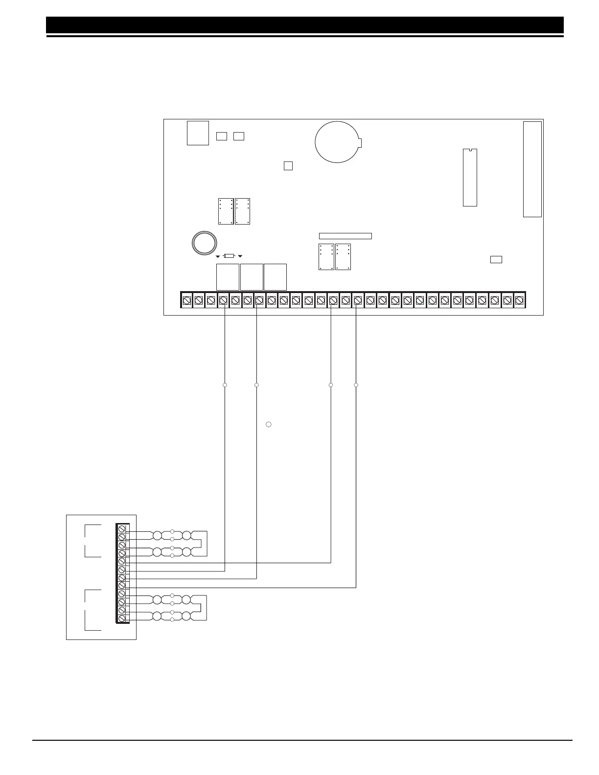
EARTH GROUND
AUX POWER
ZONE B
ZONE A
B 1
B 2
B 2
B 1
A 2
A 1
A 2
A 1
Zone A
Zone B
Dual Style D Initiating Module
Model 869
12 VDC Supply
25mA Standby Current
75mA Alarm Current
Heat detectors, manual pull
stations, or any other UL listed
shorting device.
Unlimited number of units.
J4
J16
Command Processor Reset
K4
J11J12
DD, MPX
Selection
Tamper Header
AC
1
234
56
78
10 11 12
13
14
15
16
17
18
19
AC +B -B
BELL
GND
SMK
GND
9
RED
YEL GRN BLK
20
21
22 23 24 25
26
27 28
Z1 Z2
GND
GND
GND
GND
Z3
Z4 Z5 Z6 Z7 Z8 Z9- Z9+ Z10- Z10+
K2
Phone Jack Connector
J3
Lithium Battery
K7
K6
Relay Output 1
Use Model 305
Relay Output 2
Use Model 305
J6
J2
= Supervised Circuit
S
S S S S
S
S
S
S
S
S
S
S
34.3 Dual Style D Zone Module installation