System Wiring Diagrams
38
XR2400F Installation Guide
Digital Monitoring Products www.dmpnet.com 2500 N. Partnership Boulevard Springfield, MO 65803
1
2
3
4
56
Panel Auxiliary Power - Terminal 7
Panel Common - Terminal 10
Supervisory Zone Input - Zone +
Gray - Relay #1 Common
Orange - Relay #1 Normally Open
Gray - Relay #2 Common
Orange - Relay #2 Normally Open
Note 1
Note 1
RJ31X Telco Jack
DCX Systems
STU-2Z
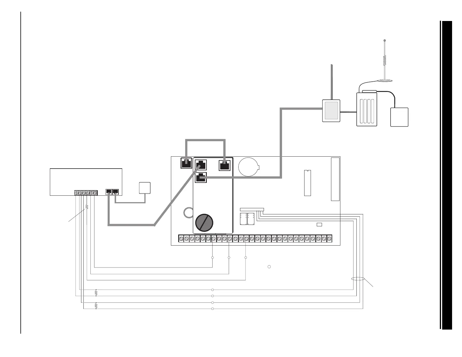
Note 1: Use EOL Termination Assembly
P/N 21024-0001 (2.2k 1/2 W Resistor).
Model 430
Output Harness.
Use EOL Termination
Assembly P/N 21024-0003
(590 Ω 1/2 W Resistor).
J4
Battery Only Restart CR7
J16
Command Processor Reset
Output Header J2
All outputs must be connected
to devices located within the
same room as the control panel.
K4
J11J12
Ground Start Relay
Use Model 305
DD, MPX
Selection
Tamper Header
AC
1
234
56
78
10 11 12
13
14
15
16
17
18
19
AC +B -B
BELL
GND
SMK
GND
9
RED
YEL GRN BLK
20
21
22 23 24 25
26
27 28
Z1 Z2
GND
GND
GND
GND
Z3
Z4 Z5 Z6 Z7 Z8 Z9- Z9+ Z10- Z10+
Answering Machine
Bypass Relay
Use Model 305
K2
Phone Jack Connector
J3
Lithium Battery
K7
K6
Relay Output 1
Use Model 305
Relay Output 2
Use Model 305
EPROM Socket
J6 Interface Connector
J6
J2
CELLULAR
TRANSCEIVER
CELLULAR
DATA
INTERFACE
AUXILIARY
POWER
SUPPLY
CELLULAR
ANTENNA
The Secure-Comª Cellular System
must be connected to a separate power
supply. Only for supplementary use.
= Supervised Circuit
S
S S S
S
S
S
S
34.6 Cellular backup installation for Derived Channel burglary