11
Installation
XR2400F Installation
Guide
2500 N. Partnership Boulevard Springfield, MO 65803 www.dmpnet.com Digital Monitoring Products
Power supply operating current 200 mA
Other standby current + _______ mA
1. Total standby current = _______ mA
No. of standby hours required X _______ hr
2. Total standby (mA.hr required) = _______ mA.hr
3. Total alarm current = _______ mA
Total alarm current X .25 = _______ mA.hr
(.25 = 5 minute alarm)
Total standby (required) + _______ mA.hr
Total = _______ mA.hr
X .001
4. Total required Amp.hrs = _______
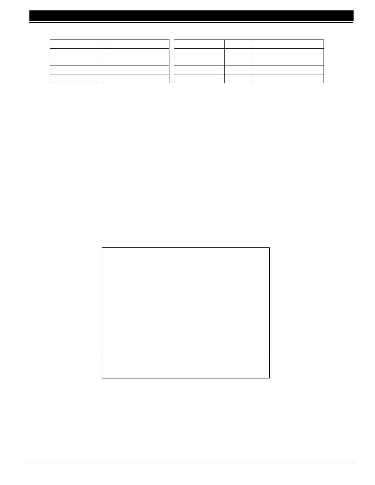
9.3 504-24 Condition Chart
Table 2: 504-24 Conditions
9.4 504-24 UL Listings
For UL 603 Power Supplies for Burglary Alarm Systems and UL294 Power Supplies for Access Control System
applications: Voltage Range of 22.9 to 25.5 VDC.
For UL1481 Power Supplies for Fire Protective Signaling the following maximum battery standby Ampere hours
apply for 24 hours of battery backup: Battery Standby Maximum: 49.2 AH
Output Voltage: 24 VDC
Output Current: 1.5A standby, 4 Amp alarm
9.5 24 VDC NAC Standby Battery Calculations
The following calculation defines the total number of standby battery Amp.hours required to support operation of
the NACs and any other devices attached to the 504-24 power supply. From this calculation, assemble the
appropriate number of batteries that will just exceed the calculated total Amp/hour requirement. The 866 NACs
receive power for internal operation from the XR2400F panel and do not enter in this calculation themselves.
1. Add all standby current values including the power supply operating current.
2. Multiply the total standby current by the number of standby hours needed.
3. Add all alarm current values from the notification appliances attached to the 866 NACs and multiply by 0.25.
4. Add the total alarm mA. hour with the total standby mA. hour and then multiply this number by .001.
Table 3: Battery Calculations
9.6 Connection
The 24 VDC power supply is completely pre-wired. Refer to the following 504-24 wiring diagram for specific wire
connections.
LED Status Condition
AC LED (GRN) ON AC Good
AC LED (GRN) OFF AC Bad
DC LED (RED) ON AC Good, Battery Good
DC LED (RED) OFF AC Good, Battery Bad
Condition 504-24
AC Trouble Approx. 102 VAC
Battery Trouble Below 23.6 VDC
Battery Restoral Above 25.0 VDC
Battery Cutoff Below 20.4 VDC