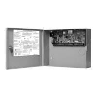
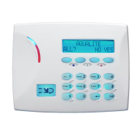
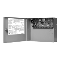
Do you have a question about the DMP Electronics XR500N SERIES and is the answer not in the manual?
Lists available communication methods for the panel, including network and dialer.
Details connecting LX-Bus devices and interface cards to the XR500 Series panel.
Highlights important safety and installation warnings for the XR500 Series panel.
Illustrates the connections for the XR500 Series panel and its associated modules.
Provides instructions for securely mounting the XR500 Series panel enclosure.
Guides on installing keypads and expansion modules for the XR500 Series system.
Details wiring and connection guidelines for LX-Bus and Keypad Bus devices.
Instructions for connecting AC power to terminals 1 and 2 on the XR500 Series panel.
Lists compatible transformer models and requirements for the XR500 Series panel.
Details connecting batteries to terminals 3 and 4 for secondary power.
Instructions for properly grounding the XR500 Series panel for transient suppression.
Provides a table for calculating power requirements for the XR500 Series and its accessories.
Guides on selecting the correct batteries for 24, 60, or 72 hours of standby power.
Explains connecting and supervising the bell output terminals for alarm signals.
Details connecting 4-wire smoke detectors and other powered devices to terminals 11 and 12.
Describes the function of terminals 13-24 for the XR500 Series burglary protection zones.
Describes the two resettable 2-wire powered zones (9 and 10) for smoke detectors.
Lists compatible 2-wire smoke detectors with manufacturer, model, and zone mapping.
Provides wiring details for the Model 431 Output Harness for relay access.
Explains how to configure the J22 header for LX-Bus, Wireless Bus, or RS-232 operation.
Describes the J21 serial connector for PC log reporting and panel programming.
Guides on connecting a computer to the panel's J21 serial connector.
Guides on connecting the XR500 Series panel to the telephone network via RJ connectors.
Explains how to use the J16 header to reset the XR500 Series microprocessor.
Details the J4 header for tamper switch wiring and enclosure security.
Lists compatible battery models and their standby time ratings for the XR500 Series.
Outlines Path 1 programming for CELL-only communication with security options.
Details line security configurations for XR500N/XR500E panels.
Outlines Path 1 programming for CELL-only communication with security options.
Specifies wiring requirements according to NEC and NFPA standards for fire systems.
Details transformer types and current limits for fire system installations.
Details power supply limitations for commercial fire installations.
Requirements for standby battery and telephone connections for remote systems.
Table of approved notification appliances and maximum number usable.
Configurations for fire systems using NET or CELL communication.
Requirements for powered burglary devices and sounding devices in combined systems.
Outlines DACT system configurations using various communication paths.
Specifies bell output programming for steady burglary and pulsed/temporal fire alarms.
Introduces FDNY specifications for IP communication in fire alarm installations.
Details NET/CELL primary/secondary communication configurations for FDNY.
Outlines digital dialer primary and network secondary communication for FDNY.
Specifies programming for digital dialer communication with network backup.
Details programming options for reducing false alarms according to SIA CP-01-2010.
Lists minimum system requirements for SIA CP-01-2010 compliance.
| Brand | DMP Electronics |
|---|---|
| Model | XR500N SERIES |
| Category | Control Panel |
| Language | English |

