Digital Monitoring Products XR500 Series Installation Guide
52
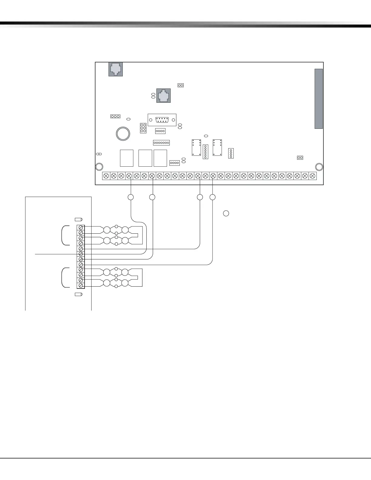
WIRING DIAGRAMS
36.14 Dual Style D Zone Module Installation
J6
Interface
Card
Expansion
Connector
XR500 Series
Command Processor™
Panel
AC
12345678 10 11 12 13 14 15 16 17 18 199202122 23 24 25 26 27 28
+B BELL GND SMK GNDRED YEL GRN BLK Z1 Z2 Z3 Z4 Z5 Z6 Z7 Z8 Z9+ Z9– Z10+ Z10–AC –B GND GND GNDGND
K6 K7
J3
J10
J22
Battery
Start
J23
J21
RS-232
J8
J4
Tamper
J16
Reset
J11
J2
J1
GND
Fault A
GND
Fault B
A1
A1
A2
A2
Zone A
GND
Zone B
B2
B2
B1
B1
Zone A
Zone B
Dual Style D Initiating Module
DMP Model 869
25mA Standby, 75mA Alarm
@ 12 VDC
Heat Detectors, manual pull stations, or any other
listed shorting device. Unlimited number of units.
S
S
Aux Power
S
S
S
S
S
S
Model 869
S = Supervised Circuit
SS S S
R
L
X
Regulated
12 VDC
J12
75VA
50VA
 Loading...


