Digital Monitoring Products XR500 Series Installation Guide
56
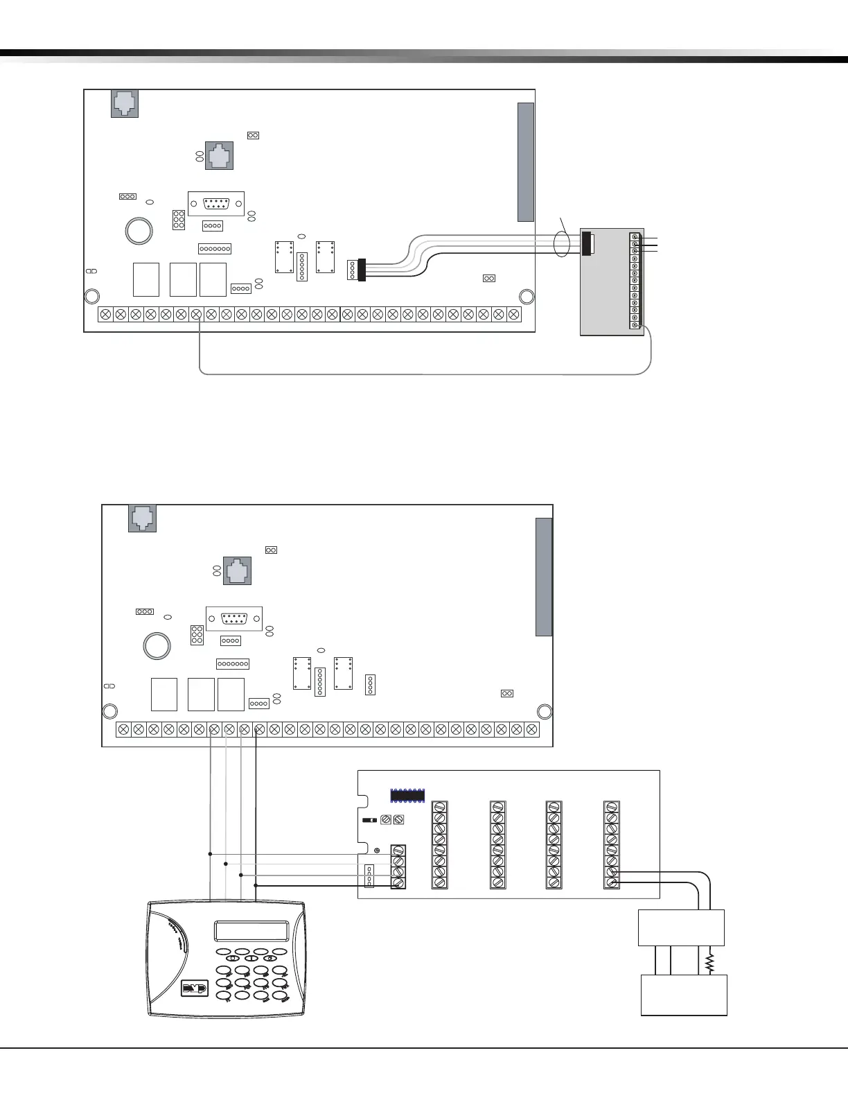
WIRING DIAGRAMS
36.18 Model 860 Relay Module Connection
J6
Interface
Card
Expansion
Connector
XR500 Series
Command Processor™
Panel
J2 Output Header
All outputs must be located
within the same room as
the control panel.
AC
12345678 10 11 12 13 14 15 16 17 18 199202122232425262728
+B BELL GND SMK GNDRED YEL GRN BLKZ1Z2Z3Z4Z5Z6Z7Z8 Z9+ Z9– Z10+Z10–AC –B GND GND GNDGND
K6 K7
J3
J10
J22
tery
J23
J21
RS-232
J4
Tamper
J16
Reset
J11
J2
J1
R
L
X
{
{
{
{
+12 VDC
Relay 4
Relay 3
Relay 2
Relay 1
Common
J2
Model 860
Relay Module
Relay contact rating:
1 Amp @ 30 VDC, resistive
4-wire
Harness
Assembly
1
2
3
4
RED
YEL
GRN
BL K
N/C
N/O
J12
75VA
50VA
36.19 Powered Burglary Devices
J6
Interface
Card
Expansion
Connector
XR500 Series
Command Processor™
Panel
AC
12345678 10 11 12 13 14 15 16 17 18 199202122232425262728
+B BELL GND SMK GNDRED YEL GRN BLKZ1Z2Z3Z4Z5Z6Z7Z8 Z9+ Z9– Z10+ Z10–AC –B GND GND GNDGND
K6 K7
J3
J10
J22
Battery
Start
J23
J21
RS-232
J8
J4
Tamper
J16
Reset
J11
J2
J1
R
L
X
Green
Black
Red
Yellow
J14
J12J10
J7
J5
TXD
J2
KYPD LX
TENS ONES
Z13+
Z13-
Z14+
Z14-
Z15+
Z15-
Z16+
Z16-
Z9+
Z9-
Z10+
Z10-
Z11+
Z11-
Z12+
Z12-
Z5+
Z5-
Z6+
Z6-
Z7+
Z7-
Z8+
Z8-
Z1+
Z1-
Z2+
Z2-
Z3+
Z3-
Z4+
Z4-
BLK
GRN
YEL
RED
Green
Black
Red
Yellow
J3
12 VDC
1k
EOL
Zone Expander
7060 Keypad
PIR or
Glassbreak
Zone
Connection
+–
505-12 Power
Supply
+–
J12
75VA
50VA

 Loading...


