Digital Monitoring Products XR500 Series Installation Guide
48
WIRING DIAGRAMS
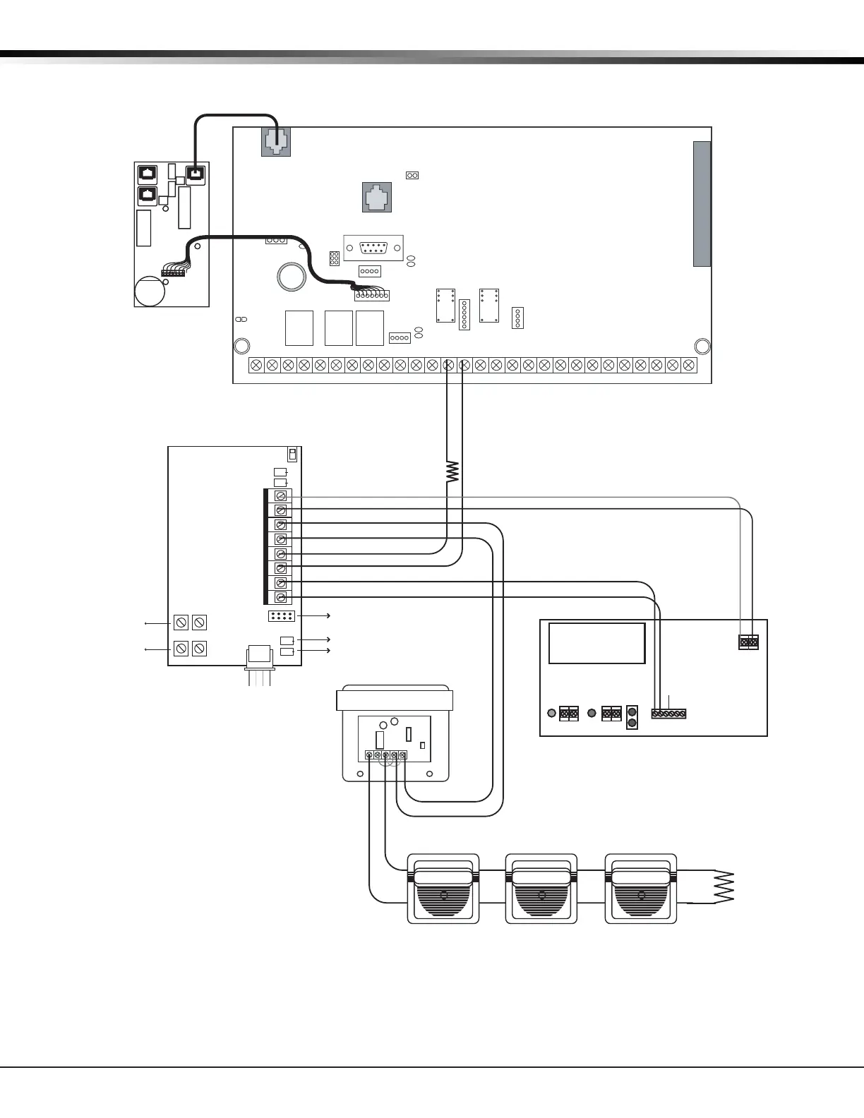
36.10 867 Class B Style W Multiple Notication Appliance Circuit
AC
1234 5678 10 11 12 13 14 15 16 17 18 199202122232425262728
+B BELL GND SMK GNDRED YEL GRN BLKZ1Z2Z3Z4Z5Z6Z7Z8 Z9+ Z9- Z10+ Z10-AC -B GND GND GNDGND
K6 K7
Output 1
Output 2
J3
Phone Line
J10
J22
LX-Bus
Battery
Start
J21
RS-232
Power LED
J8
PROG
J4
Tamper
Out2
J11
3
4
5
6
J2
J1
Ethernet
XR500 Series Command
Processor™ Panel
PANEL
MAIN BACKUP
P3
J4
J5
K1
J1
F2
F1
J2
K2
P10
DS1
Buzzer
+
–
Model 310
1K EOL
Normal/Silence Switch
Ground Fault LED
Bell Trouble LED
Bell In + 1
Bell In - 2
Bell Out + 3
Bell Out - 4
Bell Trouble 5
Bell Trouble 6
PWR Mon. 7
Mon. RTN 8
TENS ONES
TENS ONES
Bell Relay
Address
Supervisory
Address
Bell Ring Style (Steady)
Power Supply Monitor LED
Data LED
505-12 Power
Supply
J6
+ DC -
AC
Trouble
Batt
Trouble
J4
J3J2
Green
LED
AC
AC
+ BAT -
Red
LED
DC
12 VDC @ 5 Amps
Battery
Start
The Auxiliary Power Supply and Notification
Circuit Module trouble contact zone must be
programmed as a Supervisory Type zone and
must be selected for display in the keypad
status list.
Auxiliary Power Supply must be Listed for Fire
Protective Signaling Service. Power Supplies
must have battery backup.
LX-Bus Wiring
Model 308
10K EOL
Listed, Polarized
Notification Appliances
DMP Model 867
30mA @ 12 VDC
The 867 must have its
own independent
address ranging from
500 to 999. A
Supervisory zone must
be programmed into the
panel to properly
supervise each module.
SM-12/24 Module
When using an SM Sync Module, the
maximum current is 3 Amps.
See the Notification Appliance
section for a list of appliances.
Sync module required when using multiple notification appliances
J6 Interface
Card
Expansion
Connector
J23
R
L
X
J12
75VA
50VA

 Loading...


