XR500 Series Installation Guide Digital Monitoring Products
11
INSTALLATION
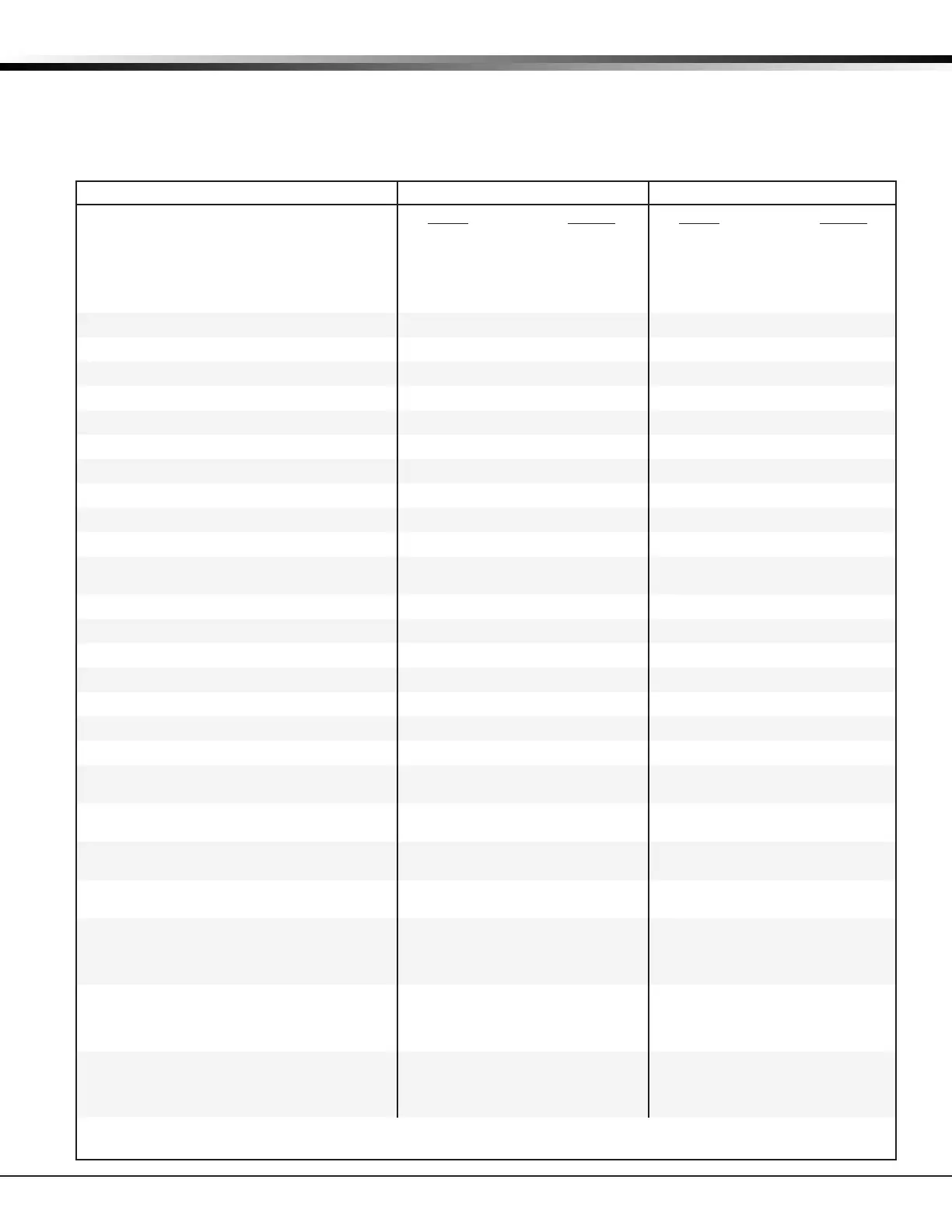
6.8 XR500 Series Power Requirements
During AC power failure, the XR500 Series panel and all connected auxiliary devices draw their power from the battery.
All devices must be taken into consideration when calculating the battery standby capacity. The following table lists
the XR500 Series panel power requirements. You must add the additional current draw of keypads, zone expansion
modules, smoke detector output, and any other auxiliary devices used in the system for the total current required. The
total is then multiplied by the number of standby hours required to calculate the total ampere-hours required.
Standby Battery Power Calculations Standby Current Alarm Current
XR500 Series Control Panel
Relay Outputs 1-2 (ON)
Switch Grounds 3-6 (ON)
Active Zones 1-8
Active Zones 9-10
2-Wire Smoke Detectors
Panel Bell Output
Qty 1_
Qty ______
Qty ______
Qty ______
Qty ______
Qty ______
x 180mA
30mA
5mA
1.6mA
4mA
0.1mA
180 mA
______
______
______
______
______
Qty 1_
Qty ______
Qty ______
Qty ______
Qty ______
Qty ______
x 180mA
30mA
5mA
2mA*
30mA
0.1mA
1500mA
180 mA
______
______
______
______
______
______mA
893A Dual Phone Line Module Qty ______ x 12mA ______ Qty ______ x 50mA ______
461 Interface Adaptor Card 7mA ______ 7mA ______
462N Network Interface Card Qty ______ x 50mA ______ Qty ______ x 50mA ______
462P Printer Interface Card Qty ______ x 50mA ______ Qty ______ x 50mA ______
463C CDMA Cellular Communicator
Qty ______ x 22mA ______ Qty ______ x 22mA ______
464-263C CDMA Cellular Communicator
Qty ______ x 15mA ______ Qty ______ x 48mA ______
464-263H HSPA+ Cellular Communicator
Qty ______ x 15mA ______ Qty ______ x 48mA ______
481 Expansion Interface Card Qty ______ x 15mA ______ Qty ______ x 15mA ______
1100X Wireless Receiver Qty ______ x 46mA ______ Qty ______ x 46mA ______
1100XH Wireless High Power Receiver Qty ______ x 160mA ______ Qty ______ x 160mA ______
860 Relay Output Module (one relay active)
All four relays active
Qty ______ x 34mA
138mA
______
______
Qty ______ x 34mA
138mA
______
______
865 Style Y or Z Notication Module Qty ______ x 26mA ______ Qty ______ x 85mA ______
866 Style W Notication Module Qty ______ x 45mA ______ Qty ______ x 76mA ______
867 LX-Bus Style W Notication Module Qty ______ x 30mA ______ Qty ______ x 86mA ______
869 Dual Style D Initiating Module Qty ______ x 25mA ______ Qty ______ x 75mA ______
630F Remote Fire Command Center Qty ______ x 63mA ______ Qty ______ x 92mA ______
7060/7160 Thinline/7060A Aqualite Keypad Qty ______ x 72mA ______ Qty ______ x 80mA ______
7063/7163 Thinline/7063A Aqualite Keypad Qty ______ x 85mA ______ Qty ______ x 100mA ______
7070/7170 Thinline/7070A Aqualite Keypad
Active Zones (EOL Installed)
Qty ______ x 72mA
1.6mA
______
______
Qty ______
Qty ______
x
x
87mA
2mA*
______
______
7073/7173 Thinline/7073A Aqualite Keypad
Active Zones (EOL Installed)
Qty ______ x 85mA
1.6mA
______
______
Qty ______
Qty ______
x
x
100mA
2mA*
______
______
7872 Graphic Touchscreen Keypad
Active Zones (EOL Installed)
Qty ______
Qty ______
x
x
145mA
1.6mA
______
______
Qty ______
Qty ______
x
x
215mA
2.0mA
______
______
7873 Graphic Touchscreen Keypad
Active Zones (EOL Installed)
Qty ______
Qty ______
x
x
143mA
1.6mA
______
______
Qty ______
Qty ______
x
x
243mA
2.0mA
______
______
734 Wiegand Interface Module
Active Zones (EOL Installed)
Annunciator (ON)
Qty ______
Qty ______
x
x
15mA
1.6mA
______
______
Qty ______
Qty ______
Qty ______
x
x
x
15mA
2mA*
20mA
______
______
______
734N Wiegand Interface Module
Active Zones (EOL Installed)
Annunciator (ON)
Wiegand Reader
Qty ______
Qty ______
Qty ______
x
x
x
146mA
1.6mA
200mA
______
______
______
Qty ______
Qty ______
Qty ______
Qty ______
x
x
x
x
148mA
2mA*
20mA
200mA
______
______
______
______
734N-WiFi Wiegand Interface Module
Active Zones (EOL Installed)
Annunciator (ON)
Wiegand Reader
Qty ______
Qty ______
Qty ______
x
x
x
146mA
1.6mA
200mA
______
______
______
Qty ______
Qty ______
Qty ______
Qty ______
x
x
x
x
148mA
2mA*
20mA
200mA
______
______
______
______
Copy Sub-Totals to next page Sub-Total Standby ______mA Sub-Total Alarm ______mA
*Based on 10% of active zones in alarm.

 Loading...


