Digital Monitoring Products XR500 Series Installation Guide
18
INSTALLATION
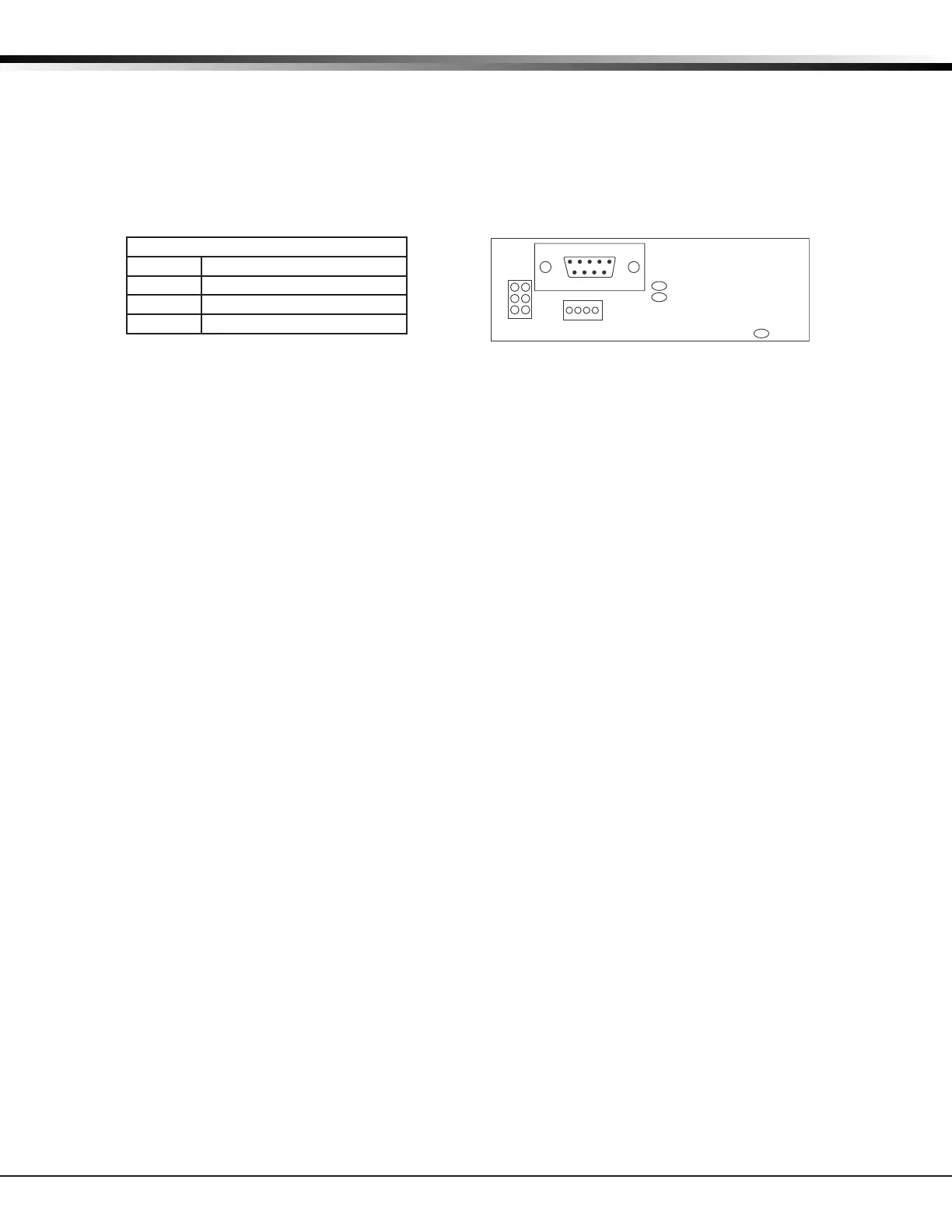
J23 6-Pin Header
14.1 Description
The XR500 Series panel supports RS-232, LX-Bus, and DMP Wireless operation. Only one operation can function at a
time. Install a jumper on one pair of J23 headers to indicate how the panel is programmed to operate. Refer to the
table below when installing a jumper on J23. When a jumper is installed or moved on the 6-pin header, briey reset
the panel using the J16 jumper to activate the selected operation.
Note: Only one operation, RS-232, LX-Bus, or DMP Wireless can function at a time.
J23 6-Pin Header
Letter Operation
R Standard RS-232
L LX-Bus
X 1100 Series DMP Wireless
J22 LX-Bus Expansion Connector
15.1 Description
The XR500 Series panel supports up to 500 wireless bus zones or up to ve LX-Bus circuits. Each Interface card
LX-Bus circuit provides 100 expansion zones. The maximum number of LX-Bus zones available on a fully populated
panel is 500. Use LX-Bus J22 Header for 100 zones. Install a single Interface Card Connector on the board to support
100 additional zones for a total of 200 zones. To install up to ve Interface Cards install a Model 461 Interface
Adaptor Card.
15.2 J22 LX-Bus Header
Note: Only one connector, J21 or J22 can function at a time. Either use J21 to connect a serial device for PC Log
Reporting, or use J22 to connect an LX-Bus or DMP Wireless device. Operation is determined by where you
install the jumper on the J23 6-Pin header. See the Connecting LX-Bus and Keypad Bus Devices section for
maximum wiring distances.
For each connection, respect wire colors when connecting devices and use all four wires. After placing the
jumper on the J23 6-Pin header to enable the required operation, briey reset the panel using the J16 jumper
to activate operation.
Wireless Bus Operation: Place a jumper on the two pins next to the letter “X” on the J23 6-Pin header. When
using J22 as a wireless bus, connect a DMP Model 300 4-wire Harness to the J22 4-pin header labeled LX. Connect
the other end to the J3 header on the 1100X or 1100XH Wireless Receiver. This provides up to 500 wireless zones
numbered 500 to 999. Refer to the 1100X Wireless Receiver Install Guide (LT-0708) or the 1100XH Wireless Receiver
Install Guide (LT-0970).
LX-Bus Operation: Place a jumper on the two pins next to the letter “L” on the J23 6-Pin header. When using J22 as
an LX-Bus, connect a DMP Model 300 4-wire Harness to the J22 4-pin header labeled LX. This provides the rst 100
LX-Bus zones numbered 500-599. No LX-Bus Interface Card is required.
Note: Do NOT use shielded wire when using the J22 LX-Bus Header.
RS-232 Operation: Place a jumper on the two pins next to the letter “R” on the J23 6-Pin header and refer to J21
Serial Connector.
Figure 8: J23 6-Pin Header
LEDs
Xmit
Rec
J22
LX
J23
J21
RS-232
R
L
X
Overcurrent
(OVC) LED

 Loading...


