XR500 Series Installation Guide Digital Monitoring Products
53
WIRING DIAGRAMS
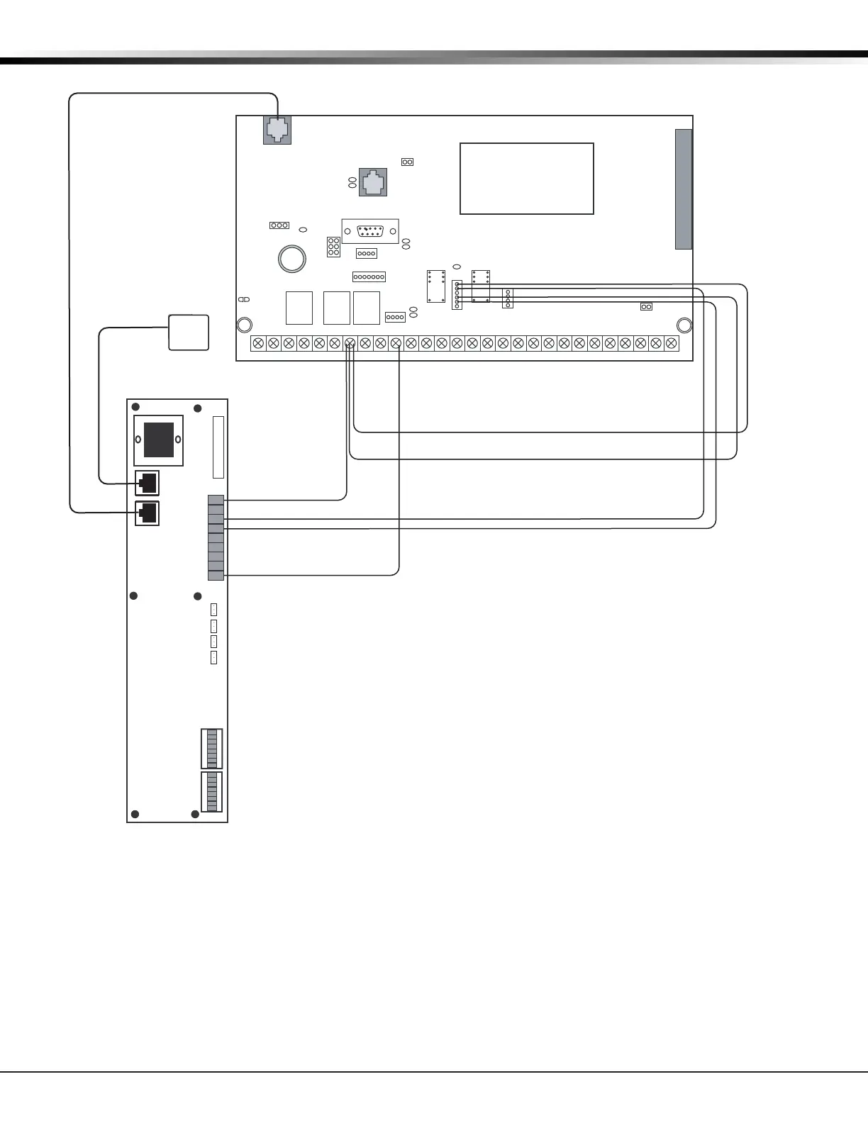
36.15 Derived Channel Installation Using Bosch D8122
Interfacing D8122 to the XR500 Series Panels
The D8122 may only be used in conjunction with telephone systems that support Derived Channel network.
For installation instructions, see the Derived Channel STUD8121A/D8122 Operation and Installation Guide.
• For Standard Line Security applications, the panel must be installed and programmed to meet burglary
alarm system requirements.
• The panel must be installed and programmed for reporting all alarm conditions through the integral
DACT or network connection to the same central station that monitors the D8122.
• The D8122 must be installed in the same enclosure as the XR500 Series panel using the supplied
mounting hardware. Refer to the STUD8121A/D8122 Operation and Installation Guide.
• Derived Channel Communication is not applicable for ULC Canadian Installations.
J6
Interface
Card
Expansion
Connector
Output Header J2 for K6 and K7 Dry Contact
Relays. All outputs must be connected to devices
located within the same room as the panel.
XR500 Series Command Processor™ Panel
AC
12345678 10 11 12 13 14 15 16 17 18 199202122 23 24 25 26 27 28
+B BELL GND SMK GNDRED YEL GRN BLK Z1 Z2 Z3 Z4 Z5 Z6 Z7 Z8 Z9+ Z9– Z10+Z10–AC –B GND GND GNDGND
K6
K7
J3
Phone Line
J10
J22
Battery
Start
J23
J21
J8
PROG
J4
Tamper
J16
Reset
J11
J2
J1
Telco Jack
R
L
X
1 2 3 4 5 6 7 8
OPEN
1 2 3 4 5 6 7 8
OPEN
SW1 (MSB) SW2 (LSB)
P1
J1
J2
P2
1 2 3
JP4
1 2 3
JP3
1 2 3
JP1
1 2 3
JP2
+ 12V
+12 VDC Out
Zone 1
Zone 2
Zone 3
Zone 4
Zone 5
CONT OUT
COMM
Output 2 Common Wire
Output 1 Common Wire
D8122
Form C Dry Contact Relays (J2)
Output Color Code–Model 431 Harness
Output 2 N/O Orange/White
Output 2 Com White/Gray
Output 2 N/C Violet/White
Output 1 N/O Orange
Output 1 Com Gray
Output 1 N/C Violet
Panel Terminal 7 Wire
Panel Common Wire
J12
75VA
50VA

 Loading...


