Digital Monitoring Products XR500 Series Installation Guide
46
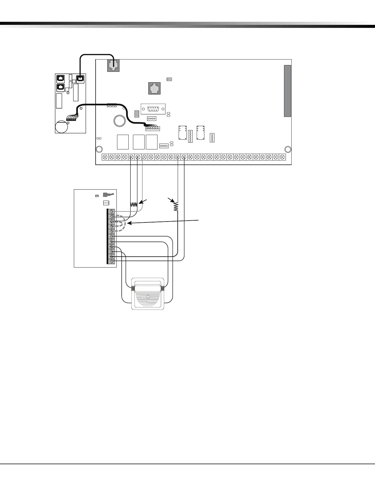
WIRING DIAGRAMS
36.8 865 Class A Style X using Single Notication Appliance
AC
1234 5678 10 11 12 13 14 15 16 17 18 199202122232425262728
+B BELL GND SMK GNDRED YEL GRN BLKZ1Z2Z3Z4Z5Z6Z7Z8 Z9+ Z9- Z10+ Z10-AC -B GND GND GNDGND
K6 K7
Output 1
Output 2
J3
Phone Line
J10
J22
LX-Bus
Battery
Start
J21
RS-232
Power LED
J8
PROG
J4
Tamper
Out2
J11
3
4
5
6
J2
J1
Ethernet
XR500 Series Command
Processor™ Panel
PANEL
MAIN BACKUP
P3
J4
J5
K1
J1
F2
F1
J2
K2
P10
DS1
Buzzer
+
–
Model 310
1K EOL
Normal
S1
J2
CR6
CR5
Bell
Silence
GND
FAULT
TRBL
J1
1
2
3
4
5
6
7
8
9
10
11
Bell Out A +
Bell Trouble
Bell Trouble
Bell Out A -
Bell Out B +
Bell Out B -
AUX PWR
GND
Alarm In
Bell PWR In +
Bell PWR In -
DMP Model 865
26mA @ 12 VDC
The 865 Notification
Appliance Circuit
aws
up to 59mA through
its Terminal 3 Alarm
Input and 26mA from
the Terminal 1
Aux Power Input.
Listed, Polarized
Notification Appliance
The Bell Output programming for Fire type
zones must be set to Temporal.
Note: Terminals 3 and 4 jumper together
to supply Bell Power from the panel
Terminals 2 and 5 jumper together to
provide Ground from the panel
See the Notification Appliance section
for a list of appliances.
Only one notification appliance may be used
when not using a sync module.
Regulated
12 VDC
J6 Interface
Card
Expansion
Connector
J23
R
L
X
J12
75VA
50VA

 Loading...


