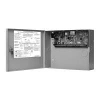
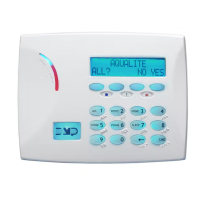
XR500 Series Installation Guide Digital Monitoring Products
31
COMPLIANCE
Access Control System Units
ANSI/UL 294
29.1 Panel Designation
The XR500 Series panels are designated stand alone units.
29.2 Tamper Protection
For listed Access Control installations, a tamper switch must be used.
29.3 Transformer
The total combined Auxiliary and Bell outputs cannot exceed 1.3 Amps with a 50 VA Transformer. The total combined
Auxiliary and Bell outputs cannot exceed 1.9 Amps with a 56 VA Transformer.
29.4 Compatible Devices
The following devices are compatible with the XR500 Series panels.
Access Control
734/734N/734N-WIFI* Wiegand
Interface Module
Proximity reader connector
OP-08CB Motion Detector Infrared sensor
PB-2 REX Button* Exit control push button
PP-6005B Proxpoint Plus® Reader Proximity reader
MP-5365 Miniprox® Reader Slimline proximity reader
PR-5455 ProxPro® II Reader Long range reader with sounder
MX-5375 Maxi-Prox™ Reader Long range reader compatible with 1351 Prox Pass
* This device has not been investigated and shall not be used in listed
installations.
Universal Fire Alarm Specications
30.1 Introduction
The programming and installation specications contained in this section must be completed when installing the
Model XR500 Series in accordance with any of the ANSI/UL or NFPA re standards. Additional specications may be
required by a particular standard. See the XR500 Series Programming Guide (LT-0679).
30.2 Wiring
All wiring must be in accordance with NEC, ANSI/NFPA 70.
30.3 Transformer
Use the Model 322/323 wire-in 16 VAC 56 VA or Model 324/324P wire-in transformer mounted within 20 feet of the
panel and connected by conduit.
For UL Commercial Fire installations, the total current combined from Auxiliary and Bell Power cannot exceed: 1.2
Amps with a 56 or 100 VA transformer; .5 Amp Max for Auxiliary Power and .7 Amp Max for Bell
For UL Residential Fire installations, the total combined Auxiliary and Bell outputs cannot exceed 1.3 Amps with a 50
VA Transformer. The total current combined from Auxiliary and Bell Power cannot exceed: 1.9 Amps with a 56 VA or
100 VA transformer
30.4 End-of-Line Resistor
The DMP Model 310 1k Ohm EOL resistor should be used on all 1k Ohm EOL re zones.
30.5 System Trouble Display
The Status List Display must include at least one keypad that displays system monitor troubles.
30.6 Fire Display
The Status List Display must include at least one keypad that displays troubles and alarms on re type zones.
 Loading...

