XR500 Series Installation Guide Digital Monitoring Products
35
COMPLIANCE
31.11 Notication Appliances
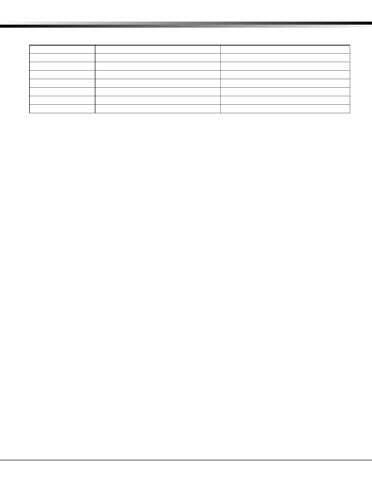
The following table indicates the approved notication appliances that can be used with the XR500 Series system.
Wheelock Model No. Description Max No. of Appliances using 56 VA/100 VA
MT-12/24 Multi-tone Horn 8
MB-G6-12 Bell, 6 inch 16
MB-G10-12 Bell, 10 inch 16
ST Series Strobe, 15/75 candela 5
HS Series Horn Strobe, 15/75 candela 5
SM-12/24-R Sync Module, Single circuit
DSM-12/24-R Sync Module, Dual circuit
31.12 Cross Zoning
When using cross zoning, there must be a minimum of two detectors installed in each protected space and the detector
installation spacing must be 0.7 times the linear spacing in accordance with National Fire Alarm Code, NFPA 72.
31.13 Ground Fault
For supervised circuits, ground fault is detected at 0 (zero) Ohms.
31.14 Wireless Testing
When using the 1100X or 1100XH Wireless Receiver for Fire Protective Signaling, after all transmitters are in
position, the WLS option of the panel’s Walk Test must be operated and all transmitters programmed for Fire (FI) or
Supervisory (SV) must show that their checkin message was received.
31.15 Wireless Supervision
When using the 1103 Universal Transmitter for Fire Protective Signaling, supervision time must be set for 3 minutes.
Supervision time cannot be set to 0 (zero).
Household Fire Warning System Units
ANSI/UL 985, NFPA 72
32.1 Bell Output Denition
The Model XR500 Series panel Bell Output must be programmed to operate steady on burglary alarms and pulsed or
temporal on re alarms.
32.2 Audible Devices
At least one listed audible device rated to operate over the voltage rate of 11.7 Vdc to 12.8 Vdc and rated at 85 DB
minimum must be used.
32.3 Auxiliary Circuits
At least one re alarm initiating device shall be used on the system. If the voltage for the device is applied by the
control unit the re alarm initiating device shall be rated to operate over the range of 11.5 Vdc to 12.7 Vdc.
32.4 Bell Cuto
The Bell Cuto time cannot be less than ve minutes.
32.5 Detect Wireless Jamming
The Detect Wireless Jamming option must be programmed YES.
32.6 Wireless Supervision Time
The Zone Information Supervision Time must be 240 minutes.
32.7 Wireless Fire Verication
When used, the Model 1161 and 1162 wireless smoke detectors must not be programmed as Fire Verication (FV)
zone type.
California State Fire Marshal Specications
33.1 Bell Output Denition
The Model XR500 Series panel Bell Output must be programmed to operate steady on burglary alarms and pulsed,
temporal, or California School Code on re alarms.

 Loading...


