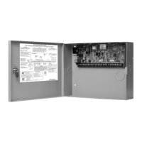
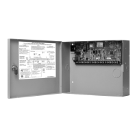
XR500 Series Installation Guide Digital Monitoring Products
i
TABLE OF CONTENTS
Product Specications Summary
1.1 Power Supply ......................................................................... 1
1.2 Communication ...................................................................... 1
1.3 Panel Zones ........................................................................... 1
1.4 Keypad Bus ............................................................................ 1
1.5 LX-Bus™ ................................................................................ 1
1.6 Outputs ................................................................................. 1
1.7 Enclosure Specications .......................................................... 1
Panel Features
2.1 Description ............................................................................ 2
2.2 Zone Expansion ...................................................................... 2
2.3 Output Expansion ................................................................... 2
2.4 Central Station Communication ................................................ 2
2.5 Encrypted Communications (XR500N/XR500E only) .................. 2
2.6 Caution Notes ........................................................................ 2
2.7 Compliance Instructions .......................................................... 2
System Components
3.1 Description ............................................................................ 3
3.2 Wiring Diagram ...................................................................... 3
3.3 Lightning Protection ................................................................ 4
3.4 Accessory Devices .................................................................. 4
3.4 Accessory Devices (continued) ................................................ 5
3.4 Accessory Devices (continued) ................................................ 6
Installation
4.1 Mounting the Enclosure .......................................................... 6
4.2 Mounting Keypads and Zone Expansion Modules ....................... 8
4.3 Connecting LX-Bus and Keypad Bus Devices ............................. 8
4.4 Wireless Keypad Association .................................................... 8
Primary Power Supply
5.1 AC Terminals 1 and 2 .............................................................. 9
5.2 Transformer Types .................................................................. 9
5.3 J12 3-Pin Header for Transformer Types ................................... 9
Secondary Power Supply
6.1 Battery Terminals 3 and 4 ....................................................... 9
6.2 Earth Ground (GND) ............................................................... 9
6.3 Battery Only Restart ............................................................... 9
6.4 Battery Replacement Period .................................................. 10
6.5 Discharge/Recharge .............................................................. 10
6.6 Battery Supervision............................................................... 10
6.7 Battery Cuto ...................................................................... 10
6.8 XR500 Series Power Requirements ......................................... 11
6.9 Standby Battery Selection ..................................................... 13
Bell Output
7.1 Terminals 5 and 6 ................................................................. 14
Keypad Bus
8.1 Description .......................................................................... 14
8.2 Terminal 7 - RED .................................................................. 14
8.3 Terminal 8 - YELLOW ............................................................ 14
8.4 Terminal 9 - GREEN .............................................................. 14
8.5 Terminal 10 - BLACK ............................................................. 14
8.6 J8 Programming Connection .................................................. 14
8.7 OVC LED .............................................................................. 14
Smoke and Glassbreak Detector Output
9.1 Terminals 11 and 12 ............................................................. 14
9.2 Current Rating...................................................................... 14
Protection Zones
10.1 Terminals 13–24 ................................................................... 15
10.2 Operational Parameters ......................................................... 15
10.3 Zone Response Time ............................................................ 15
10.4 Keyswitch Arming Zone ......................................................... 15
Powered Zones for 2-Wire Smoke Detectors
11.1 Terminals 25–26 and 27–28 .................................................. 15
11.2 Compatible 2-Wire Smoke Detector Chart ............................... 16
 Loading...

