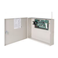
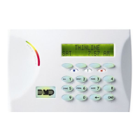
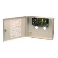
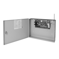
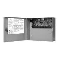
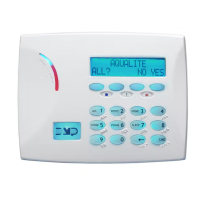
Digital Monitoring Products XR500 Series Installation Guide
ii
TABLE OF CONTENTS
Dry Contact Relay Outputs
12.1 Description .......................................................................... 17
12.2 Contact Rating ..................................................................... 17
12.3 Model 431 Output Harness Wiring ......................................... 17
Annunciator Outputs
13.1 Description .......................................................................... 17
13.2 Model 300 Harness Wiring..................................................... 17
13.3 Model 860 Relay Module ....................................................... 17
J23 6-Pin Header
14.1 Description .......................................................................... 18
J22 LX-Bus Expansion Connector
15.1 Description .......................................................................... 18
15.2 J22 LX-Bus Header ............................................................... 18
15.3 LX-Bus Interface Cards ......................................................... 19
15.4 LX-Bus LEDs ......................................................................... 19
15.5 OVC LED .............................................................................. 19
J21 Serial Connector
16.1 Description .......................................................................... 19
16.2 Computer Connection to J21 ................................................. 19
16.3 Serial Connector LEDs ........................................................... 20
J1 Ethernet Connector (XR500N/XR500E only)
17.1 Description .......................................................................... 20
17.2 Ethernet LEDs ...................................................................... 20
J3 Telephone RJ Connector
18.1 Description .......................................................................... 20
18.2 J10 893A Connector ............................................................. 20
18.3 Notication .......................................................................... 20
18.4 Phone Line Monitor ............................................................... 20
18.5 FCC Registration ................................................................... 21
Reset and Tamper Headers
19.1 J16 Reset Header ................................................................. 22
19.2 J4 Tamper Header ................................................................ 22
Listed Compliance Specications
20.1 Introduction ......................................................................... 23
Universal Burglary Specications
21.1 Introduction ......................................................................... 23
21.2 Wiring ................................................................................. 23
21.3 Transformer ......................................................................... 23
21.4 Control Outside of Protected Area .......................................... 23
21.5 Police Station Phone Numbers ............................................... 23
21.6 Bypass Reports .................................................................... 23
21.7 System Maintenance ............................................................. 23
21.8 Listed Receivers ................................................................... 23
21.9 Power Supply Supervision ..................................................... 23
21.10 Wireless Tamper ................................................................... 23
21.11 Wireless External Contact ...................................................... 23
21.12 Wireless Supervision Time ..................................................... 23
21.13 Detect Wireless Jamming ...................................................... 23
21.14 Standby Batteries ................................................................. 23
Area Information
22.1 Ownership ........................................................................... 24
22.2 Annunciation ........................................................................ 24
22.3 Trouble Display..................................................................... 24
22.4 Closing Wait ......................................................................... 24
22.5 Local Bell Supervision ........................................................... 24
Household Burglar-Alarm System Units
ANSI/UL 1023
23.1 Audible Devices .................................................................... 24
23.2 Auxiliary Circuits ................................................................... 24
23.3 Bell Cuto ............................................................................ 24
23.4 Entry Delay .......................................................................... 24
23.5 Exit Delay ............................................................................ 24
23.6 Weekly Test ......................................................................... 24
23.7 Wireless Audible Annunciation Option .................................... 24
 Loading...

