XR500 Series Installation Guide Digital Monitoring Products
7
INSTALLATION
AC
1 2 3 4 5 6 7 8 10 11 12 13 14 15 16 17 18 199 20 21 22 23 24 25 26 27 28
+B BELL GND SMK GNDRED YEL GRN BLK Z1 Z2 Z3 Z4 Z5 Z6 Z7 Z8 Z9+ Z9– Z10+Z10–AC –B GND GND GNDGND
K6 K7
Output 1 Output 2
J3
Phone Line
J10
J22
LX-Bus
Battery
Start
J23
J21
RS-232
Power
LED
J8
PROG
J4
Tamper
J16
Reset
Out1 Out2
Outputs 3-6
J11
3
4
5
6
J2
J1
Ethernet
R
L
X
Link LED
Activity LED
OVC
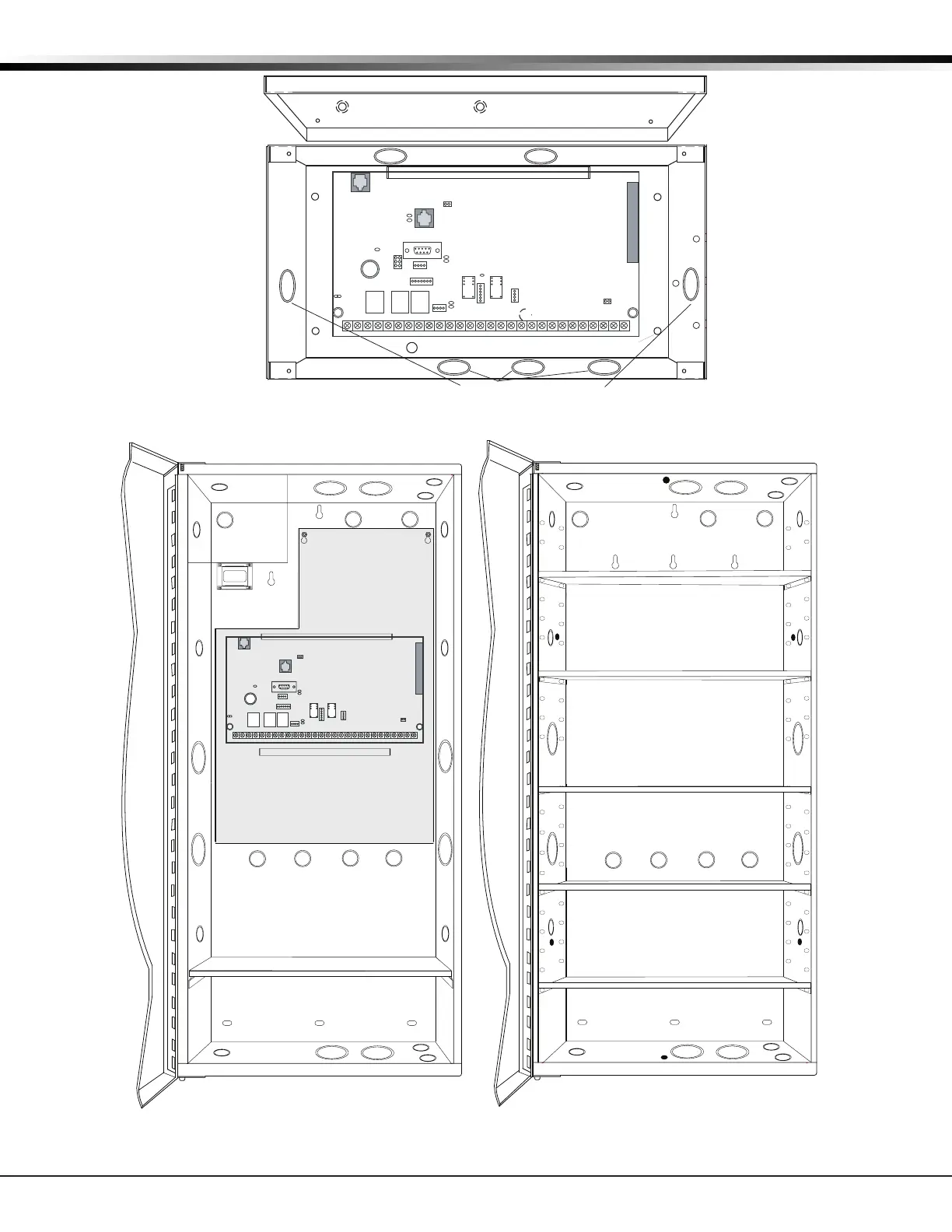
XR500 Series Panel
Dual 1/2" and 3/4" Conduit Knockouts
Lid Mounting Holes (4 places)
Lid Mounting Holes
(4 places)
Enclosure Mounting Holes (4 places)
PEMs for optional battery bracket
Figure 3: XR500 Series in Model 341 Enclosure
100 VA
Transformer
Mounting for one (1)
Zone Expansion Module.
Battery Shelf
Mounting
Plate
J6
Interface
Card
Expansion
Connector
XR500 Series
Command Processor™
Panel
AC
12345678 10 11 12 13 14 15 16 17 18 199202122232425262728
+B BELLGND SMK GNDRED YEL GRN BLKZ1Z2Z3Z4Z5Z6Z7Z8 Z9+ Z9– Z10+Z10–AC –B GND GND GNDGND
K6 K7
Output 1Output 2
J3
Phone Line
J10
J22
LX-Bus
Battery
Start
J23
J21
RS-232
Power
LED
J8
PROG
J4
Tamper
J16
Reset
Out1 Out2
Outputs 3-6
J11
3
4
5
6
J2
J1
Ethernet
Figure 4: XR500 Series in Model 352X Enclosure and Separate 352S Enclosure with Shelves

 Loading...


