Installation
19
XR2400F Installation Guide
2500 N. Partnership Boulevard Springfield, MO 65803 www.dmpnet.com Digital Monitoring Products
15.5 Connecting serial devices
Refer to the 710 Bus Splitter/Repeater Installation Sheets, LT-0310 (Document No. 0310 on DMP Fax) for
information concerning keypad and LX-Bus wiring distances and capacities.
Keypad Data Bus
The keypad data bus requires only a 4-wire cable between devices and the panel. You can connect devices in
parallel on the same cable or provide separate runs back to the panel. The maximum cable length for one
keypad can be up to 500 feet using 22 gauge wire or up to 1000 feet using 18 gauge wire. Additional keypads
installed on the same cable decrease the maximum distance at which they will operate properly.
Refer to Figure 15: Typical XR2400F Wiring Diagram for additional wiring information.
Expansion Interface Cards (Models 462N, 462P, 472, 481, and 482)
The LX-Bus provided on these cards also requires only a 4-wire cable between the card and any devices
connected to the bus. You can connect devices (zone or output expanders) together on the same cable or
provide separate runs back to the cards. You can determine the maximum length of each wire run by totaling the
number of devices against the size wire used. Up to 100 zones or relays are available on each LX-Bus.
The XR2400F supports two LX-Bus' to provide up to 200 class B style 3.5 alarm points. You can connect up to
100 Model 521LX or 521LXT smoke detectors directly to the 4-wire cable. These detectors are individually
addressable to provide specific alarm point information of a fire.
15.4 Mounting keypads and zone expanders
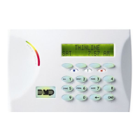
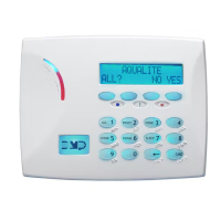
Security Command keypads have removable covers that allow you to easily mount the keypad to a wall or other
flat surface using the screw holes provided on each corner of the base. Before mounting the base, connect the
keypad wire harness leads to the keypad cable from the panel and to any device wiring run to that location.
Then attach the harness to the pin connector on the PC board, mount the base, and install the keypad cover
making sure all of the keys extend through their respective holes.
For mounting keypads on solid walls, or for applications where conduit is required, use a DMP 775 or 776
keypad conduit backbox for 770 series keypads. To provide additional protection for the keypad against
unauthorized access, you can install the 777 Plastic Keypad Cover that provides a clear 1/8" thick polycarbonate
housing with locking mechanism.
For the 790 series keypads, you can use the Model 695 1-1/2" deep or the Model 696 1/2" deep backboxes.
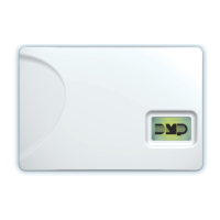
The DMP 711, 711E, 714, 715, 716, and 717 modules are each contained in molded plastic housings with
removable covers. The housing cover contains the module while the base provides you with two mounting holes
for installing the unit to a wall, switch plate, or other surface.

 Loading...
