10
Installation
XR2400F Installation Guide
Digital Monitoring Products www.dmpnet.com 2500 N. Partnership Boulevard Springfield, MO 65803
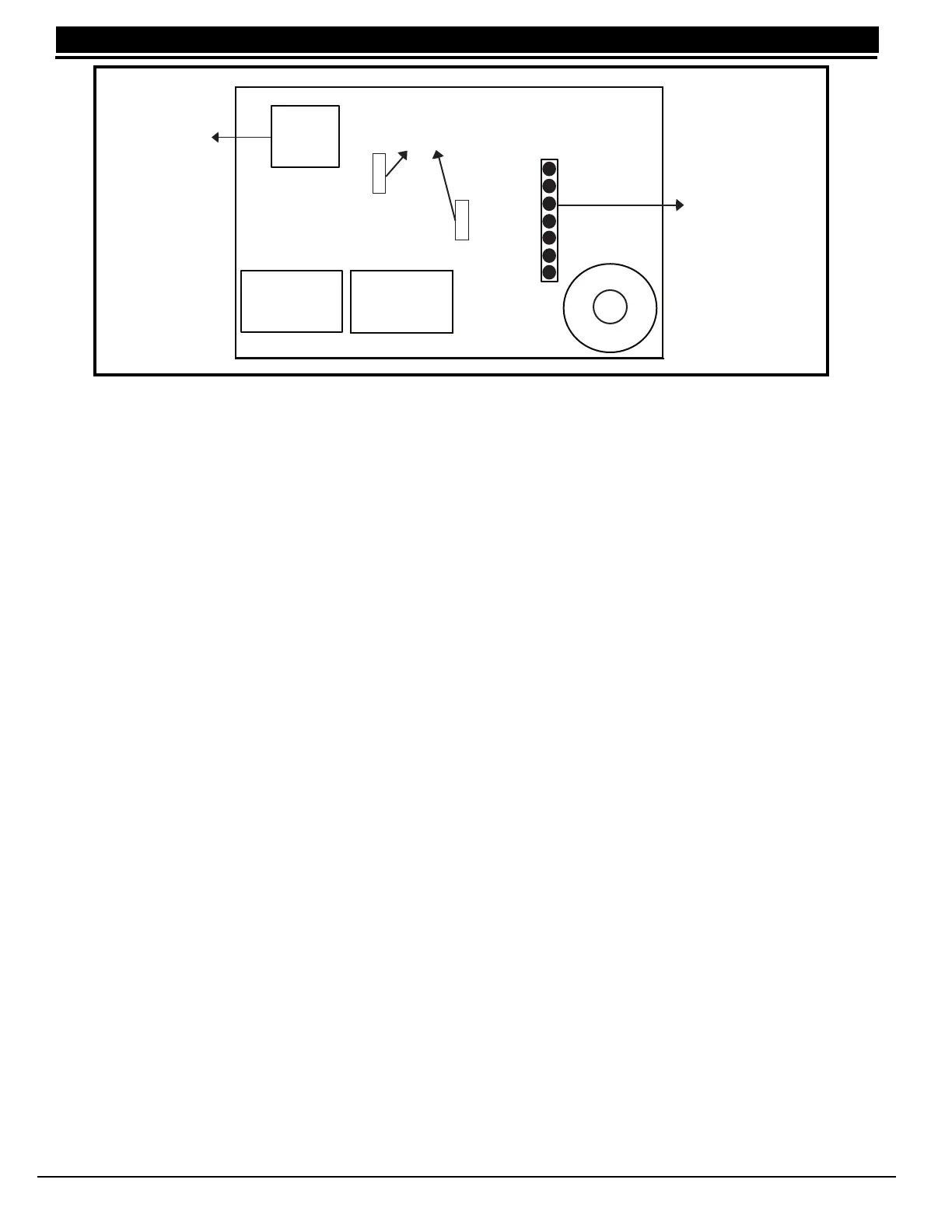
Figure 8: 893A Wiring Diagram
8.3 Jumper Settings
There are two sets of jumpers on the 893A module. When setting the module for either DD (digital dialer) or
MPX (multiplex),
both
jumpers must be set.
8.4 Digital Dialer/Multiplex
You can configure the 893A to provide two lines of digital dialer or one line of multiplex with digital dialer backup.
For multiplex operation both jumpers (J1 and J2) must be set to MPX. Also, jumpers J11 and J12 on the panel
must be set to MPX. See XR2400F Command Processor Panel Connection. The XR2400F is preset at the
factory for Digital Dialer. The Main modular jack (J4) is used for the primary dialer or multiplex line. The Backup
modular jack (J5) is used for the secondary digital dialer line.
8.5 Phone Line Monitor
The 893A uses a phone line monitor for the main and backup phone lines. When sending a report, the 893A
verifies the main phone line is working before sending. If the line is bad, the module tests the backup phone line.
The 893A sends the report on the first working phone line.
The phone line monitor has a two minute trouble delay and a one minute restore delay. Phone line trouble is
displayed in the Fire Command Center LCD Status List as a System Trouble. The Fire Command Center LCD is
factory programmed to display system troubles in the Status List.
8.6 Processor Fail Buzzer
The 893A module also monitors the panel's CPU and sounds a trouble buzzer whenever either the panel's
processor is reset using J16 or the processor stops functioning.
504-24 Power Supply
9.1 Description
The 504-24 is a power limited, switching power supply that meets UL, CSFM, NFPA, and FCC compliance
standards. Model 504-24 is rated for 24 VDC @ 4 Amps maximum and supplies power to the 866 NAC
modules.
9.2 LED's
The 504-24 has two status LED's that show the current state of power. The green LED indicates low AC input.
The red LED indicates low standby battery power after AC has failed.
P10
Panel
Main
Backup
J4 J5
J3
J2
J1
DD
MPX
DD
MPX
Communication Jumpers (Both
Jumpers must be set)
To Primary
Phone Line
To Secondary
Phone Line
Factory pre-wired
To Panel phone
jack connector J3
Processor
Stopped Buzzer
Factory Pre-wired to
Panel connector
J10