5
Installation
XR2400F Installation
Guide
2500 N. Partnership Boulevard Springfield, MO 65803 www.dmpnet.com Digital Monitoring Products
3.3 16.5 VAC Transformer
The 16.5 VAC 100 VA transformer supplies power to the XR2400F panel and is factory pre-wired. See Figure 3:
Transformers and AC Power Connection. Also refer to Figure 11: XR2400F Panel Wiring Diagram.
3.4 Earth ground from the XR2400F panel
Terminal 4 of the XR2400F panel must be connected to earth ground using 14 gauge or larger wire to provide
proper transient suppression. DMP recommends connecting to a cold water pipe or ground rod only. Do not
connect to an electrical ground or conduit, sprinkler or gas pipes, or to a telephone company ground.
Secondary Power Supply
4.1 Description
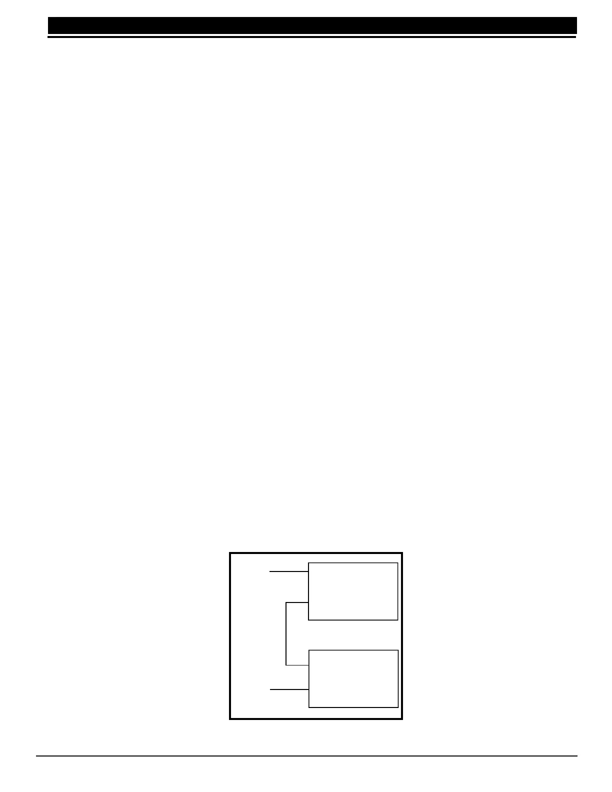
The XR2400F system includes pre-wired cables for connecting a 24 VDC battery to the 504-24 power supply
and a 12 VDC battery to the XR2400F panel. For 24 VDC battery operation to the 504-24, connect two 12 VDC
sealed lead-acid batteries in series using the included series connecting strap (See Figure 4).
Observe polarity
when connecting all batteries.
Use sealed lead-acid batteries only.
Use the DMP Model 367, 12 VDC 7.0Ah sealed lead-acid rechargeable
battery. Batteries supplied by DMP or manufactured by Eagle Picher or Yuasa have been tested to ensure
proper charging with DMP products.
Gel cell batteries cannot be used with the XR2400F panel.
4.2 Battery Connection to XR2400F Command Processor panel
For 12 VDC battery operation to the XR2400F, connect the black battery lead to the negative terminal of the
battery. The black battery wire is connected to terminal 4 of the XR2400F panel.
Connect the red battery lead to the positive terminal of the battery. The red battery wire is connected to terminal
3 of the XR2400F panel. See Figure 11: XR2400F Panel Wiring Diagram and Figure 2: XR2400F System.
You can add a second battery in parallel using the DMP Model 318 Dual Battery Harness. When wiring two
batteries with the Model 318 Dual Battery Harness, plug the red male end of the Dual Battery Harness into the
red female battery lead from the panel. Plug the black male end of the Dual Battery Harness into the black
female battery lead from the panel. Attach both female leads from the Dual Wiring Harness to the two batteries
as described above. See Table 3: Battery Calculations.
4.3 Battery Connection to the 504-24 Power Supply
The 504-24 is powered by 24 VDC. After connecting two 12 VDC batteries together using the series connecting
strap (or after installing one 24 VDC battery) connect the black battery wire to the negative terminal of the 24
VDC battery. The black battery wire is connected to the negative AC terminal of the 504-24.
Connect the red battery wire to the positive terminal of the 24 VDC battery. The red battery wire is connected to
the positive AC terminal of the 504-24.
See Figure 9: 504-24 Wiring Diagram and Figure 2: XR2400F system. Also see Battery Information section.
12
VDC
Battery
12
VDC
Battery
+
-
+
-
RED
BLACK
Series
Connecting
Strap
Figure 4: 24 VDC wiring