System Wiring Diagrams
XR2400F Installation Guide
2500 N. Partnership Boulevard Springfield, MO 65803 www.dmpnet.com Digital Monitoring Products
33
System Wiring Diagrams
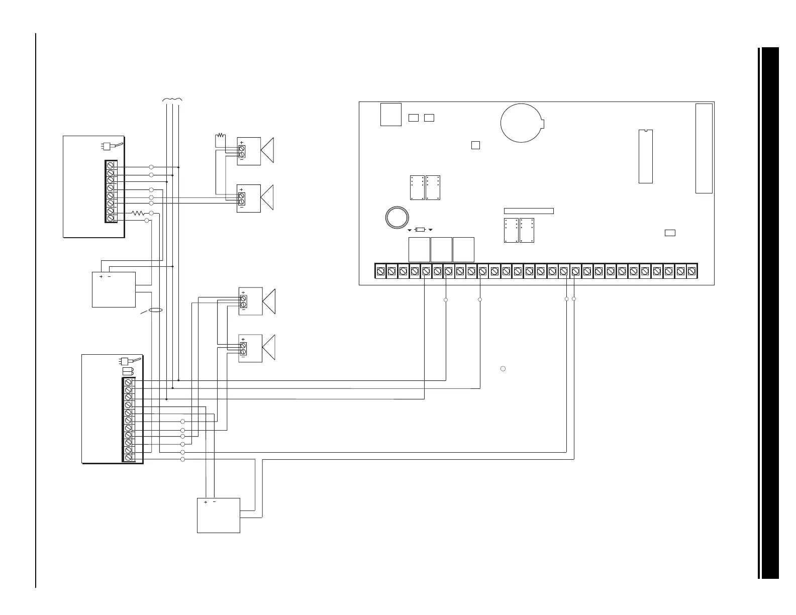
34.1 Multiple indicating circuit modules
AUXILIARY
POWER
SUPPLY
24 VDC 5 Amp
Maximum
Power Supply
Trouble Contacts
N/C
NOTE: If an auxiliary supply is not used,
terminals 3 and 4 on the 866 Indicating
Circuit Module can be jumpered together
to supply bell power from the XR200 panel.
A maximum of 1.5 Amps at 12 VDC is
available from terminal 5 of the XR200.
Auxiliary power supply must be regulated
UL listed for Fire Protection Signaling Service.
Power supplies must have battery backup.
Each 866 Indicating Circuit Module
in alarm draws up to 35mA from its
terminal 3 alarm input.
J4
J16
Command Processor Reset
K4
J11J12
DD, MPX
Selection
AC
1
234
56
78
10 11 12
13
14
15
16
17
18
19
AC +B -B
BELL
GND
SMK
GND
9
RED
YEL
GRN
BLK
20
21
22 23 24 25
26
27 28
L1 L2
GND
GND
GND
GND
L3
L4 L5 L6 L7 L8 L9- L9+ L10- L10+
Answering Machine
Bypass Relay
Use Model 305
K2
Phone Jack Connector
J3
Lithium Battery
K7
K6
Relay Output 1
Use Model 305
Relay Output 2
Use Model 305
J6
J2
The Auxiliary Power Supply and Indicating Circuit Module
trouble contact zone must be programmed as a Supervisory
Type zone and must be selected for display in the keypad
status list.
See section 10.6 in the XR200 Programming Guide (LT-0196).
= Supervised Circuit
S
S
S
S
S
1
2
3
4
5
6
7
8
Auxiliary Power
Ground
Alarm Input
Bell Power + Input
Bell Power Ð Input
Bell A + Output -
Bell A Ð Output
Bell B + Output
Bell Trouble
Bell Trouble
Bell B Ð Output
9
10
11
UL Listed, Polarized
Indicating Devices.
Style Z
Notification Circuit Module
DMP Model 865
85mA at 12 VDC
AUXILIARY
POWER
SUPPLY
Power Supply
Trouble Contacts
N/C
24 VDC 5 Amp
Maximum
S
S
1
2
3
4
5
6
7
8
Auxiliary Power
Ground
Alarm Input
Bell Power Input
Bell Output +
Bell Output -
Bell Trouble
Bell Trouble
UL Listed, Polarized
notification Devices.
10k Ω EOL Resistor
DMP Model 308
Notification Circuit Module
DMP Model 866
37mA at 12 VDC
1k Ω
Each 865 Notification Circuit Module
in alarm draws up to 85mA from its
terminal 3 alarm input.
S
S
S
S
S
S
S
S
S
S
S
To additional twenty-three 866 Indicating Circuit
Modules. Up to a maximum of twenty-five 866
modules on the XR200 panel. All modules must
be installed in a 340FC, 349, or 350 enclosure
connected by no more than 20 feet of conduit.
Style W
504-24
Power
Supply
504-24
Power
Supply