XTL/XTLC Installation Guide Digital Monitoring Products
3
system components
Installation
4.1 Mounting Location Information
A location should be selected that is centrally located between the 1100 Series transmitters used in the
installation.InstalltheXTL/XTLCawayfrommetalobjects.Mountingthepanelonornearmetalsurfaces
impairsperformance.Whenselectingthepropermountinglocationofatransmitter,refertotheLEDSurvey
Operationsectionofthespecicinstallationguideforthetransmitterbeinginstalled.
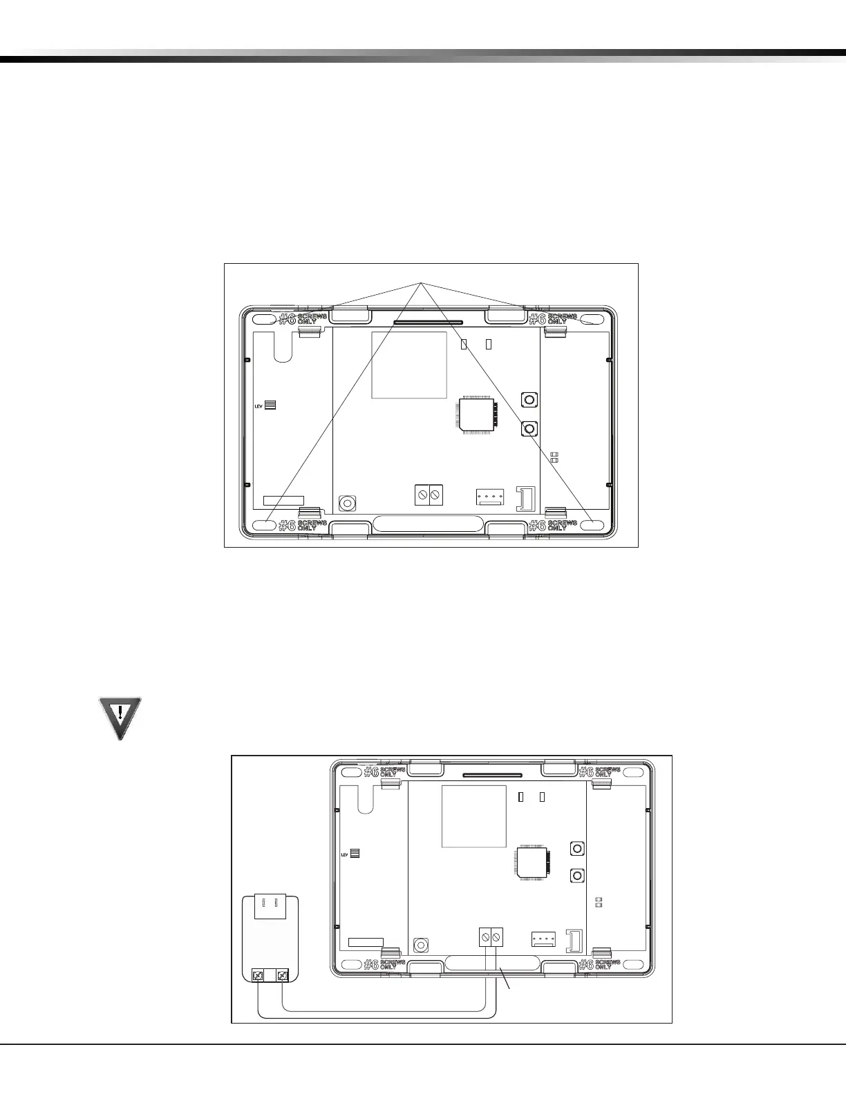
4.2 Mounting the Enclosure
TheenclosurefortheXTL/XTLCpanelmustbemountedusingtheprovided#6screwsinthefourmounting
holesshowninFigure1.Mounttheenclosureinasecure,dryplaceawayfrommetalobjectstoprotect
thepanelfromdamageduetotamperingortheelements.Mountthepanelaminimumof4feetfromany
wireless transmitters or repeaters. It is not necessary to remove the PCB when installing the enclosure.
Mounting Hole Locations
RESET
S1
LOAD
S2
BAT
J1
PROG
RED
PWR
MODEL XTL
TX RF RX
S
N
Figure 1: Mounting Hole Locations
Primary Power Supply
5.1 DC Input
MounttheXTL/XTLCpanelnearawalloutletfortheModel372-500plug-inDCpowersupply.Inaddition
topoweringthepanel,theDCplug-inpowersupplyalsochargestheback-upbattery.The372-500mustbe
locatedwithin100feetofthepanelusing22AWGwire.Usethefollowingstepstoconnecttheplug-inpower
supply:
OBSERVE POLARITY
1. Using22AWGwire,connectthepanelPWR(J2)rstterminal(+)tothepositiveterminalonthe
power supply.
2.ConnectthepanelPWR(J2)secondterminal(-)tothenegativeterminalonthepowersupply.
3.Plugthepowersupplyintoa120VoltAC,60Hzdedicatedoutletnotcontrolledbyaswitch.
Figure2:DCPowerSupplyConnection
Wire Exit for DC
Power Supply
+
+
Model 372-500
DC Plug-in
Power
Supply
Use 22 AWG for
Power Supply connection
_
_
RESET
S1
LOAD
S2
BAT
J1
PROG
RED
PWR
MODEL XTL
TX RF RX
S
N