Digital Monitoring Products XTL/XTLC Installation Guide
4
InstallatIon
Secondary Power Supply
6.1 Standby Battery
TheXTL/XTLCrechargeablebatteryisusedtoprovidebackupbatterypowerwhenDCpowerisnot
available.Thebatteryisintendedforbackuppoweronlyandnottooperatethepanelonadailybasis.If
thebatteryislow,ornotpluggedintotheJ1batteryconnector,alowbatteryconditionisindicatedbythe
panel.
Note:Ifremovingthepanelfromservice,disconnectthebackupbatteryfromthepanelconnector.
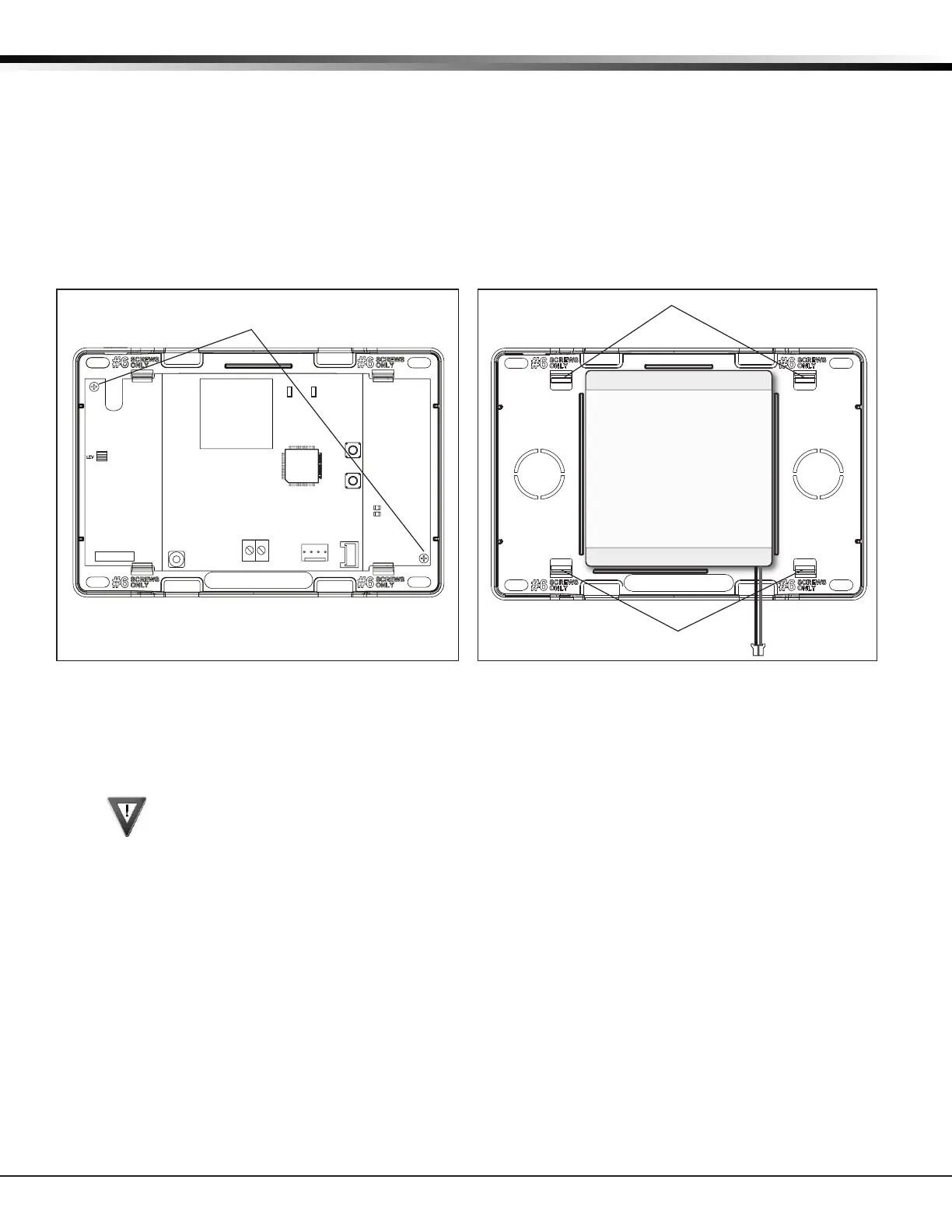
6.2 Replacement
Usethefollowingstepstoreplacethepanelstandbybattery.DMPrecommendsreplacingthebatteryevery3
years under normal use.
1.Unplugthebatteryconnector(J1)fromthepanel.
2.Ifinstalled,removethe2screwsfromthePCB.
3.LoosenthetopPCBsnaps.
4.LeanthepanelPCBforwardandliftoutfromthebottomPCBsnaps.
5. Remove and properly dispose of the used battery.
Caution:Riskofre,explosion,andburns.Donotdisassemble,heatabove212°F(100°C),
or incinerate. Properly dispose of used batteries.
6. Place the new battery into the housing base with the battery wires directed toward the bottom
rightcorner.SeeFigure2.
7.SetthePCBintothebottomsnapsandpressintothetopsnapstosecureinplace.
8.Plugthebatteryintothepanelconnector(J1).
6.3 Battery Supervision
ThepanelteststhebatteryonceeveryhourwhenDCpowerispresent.Thistestoccurs15minutespast
eachhourandlastsforveseconds.Aloadisplacedonthebatteryandifthebatteryvoltageislow,alow
batteryisdetected.IfDCpowerhasfailed,alowbatteryisdetectedanytimethebatteryvoltagefalls
below3.7V.
RESET
S1
LOAD
S2
BAT
J1
PROG
RED
PWR
MODEL XTL
TX RF RX
S
N
PCB Screw Locations
Top PCB Snaps
Bottom PCB Snaps
Battery
3.7V
Rechargeable
Battery
Figure 4: Standby Battery ReplacementFigure 3: PCB Screw Locations