(No.HD003<Rev.004>)1-13
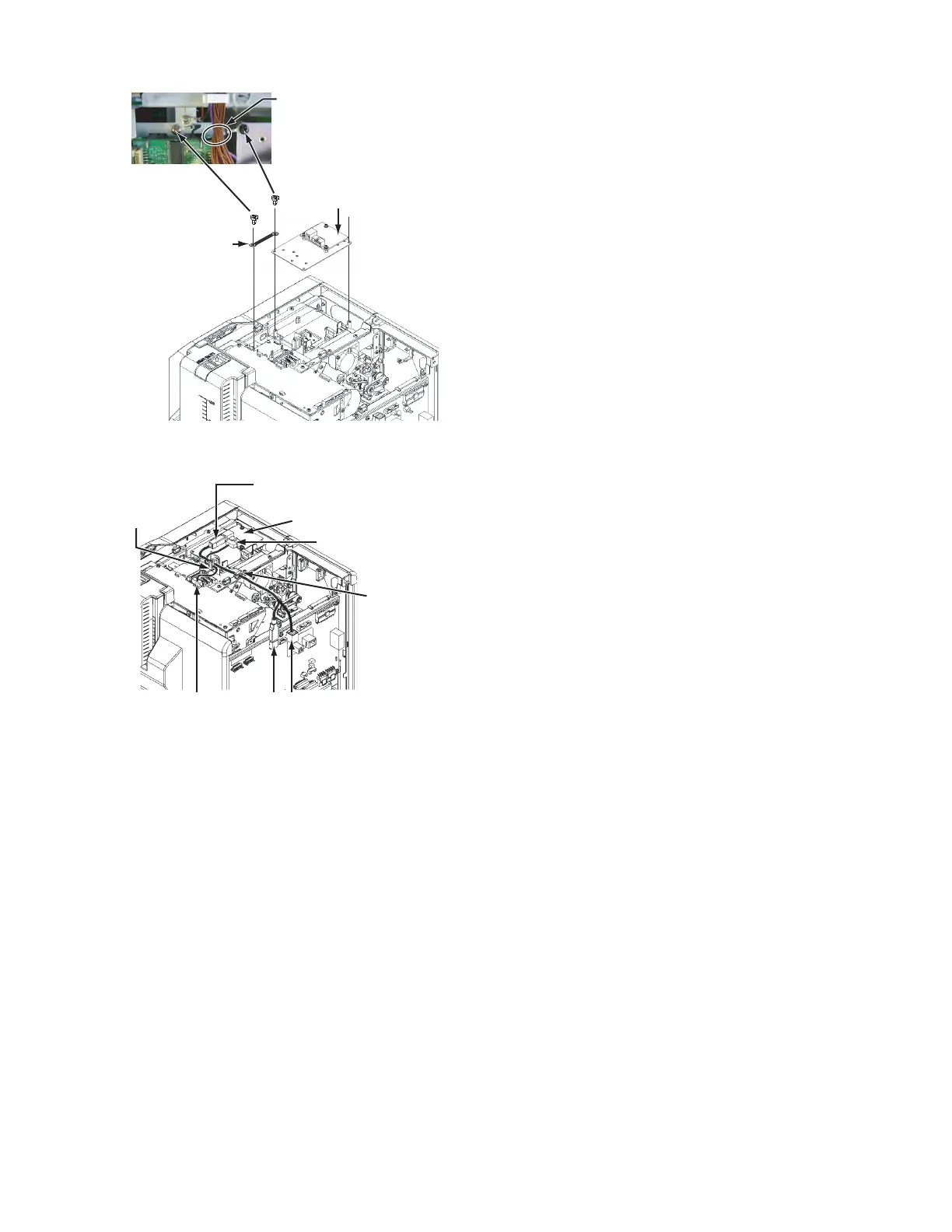
(2) Mount the IC R/W unit.
(3) Connect the wires from the IC R/W unit following the draw-
ing below.
For direct connection of the IC R/W unit and a PC, connect
to J3, not to J1.
Note that the IC R/W unit cannot be recognized on the sta-
tus monitor in the J3 connection.
2.5.6 Attaching the top cover and the rear cover
(1) Attach the top cover and the rear cover in the reverser pro-
cedure of disassembly.
Run the earth wire under
the wires from the FRONT Board.
QYSDSF3008NA x 2
IC R/W Unit
QYSDST3006NA
QUB340-07DMDM-E
Connect the supplied USB cable
and the connector J1 on the MAIN Board.
Connect the supplied wire (10-pin)
to the connector CN5 on the
IC CONTACTIFC Board.
IC R/W Unit
Wire clamp
Wire clamp
CN5 J1
J3