(No.HD003<Rev.004>)1-17
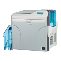
(4) Remove the two screws C attaching the side cover U-R
and side cover U-L, then remove the side cover U-R and
side cover U-L.
Fig.4
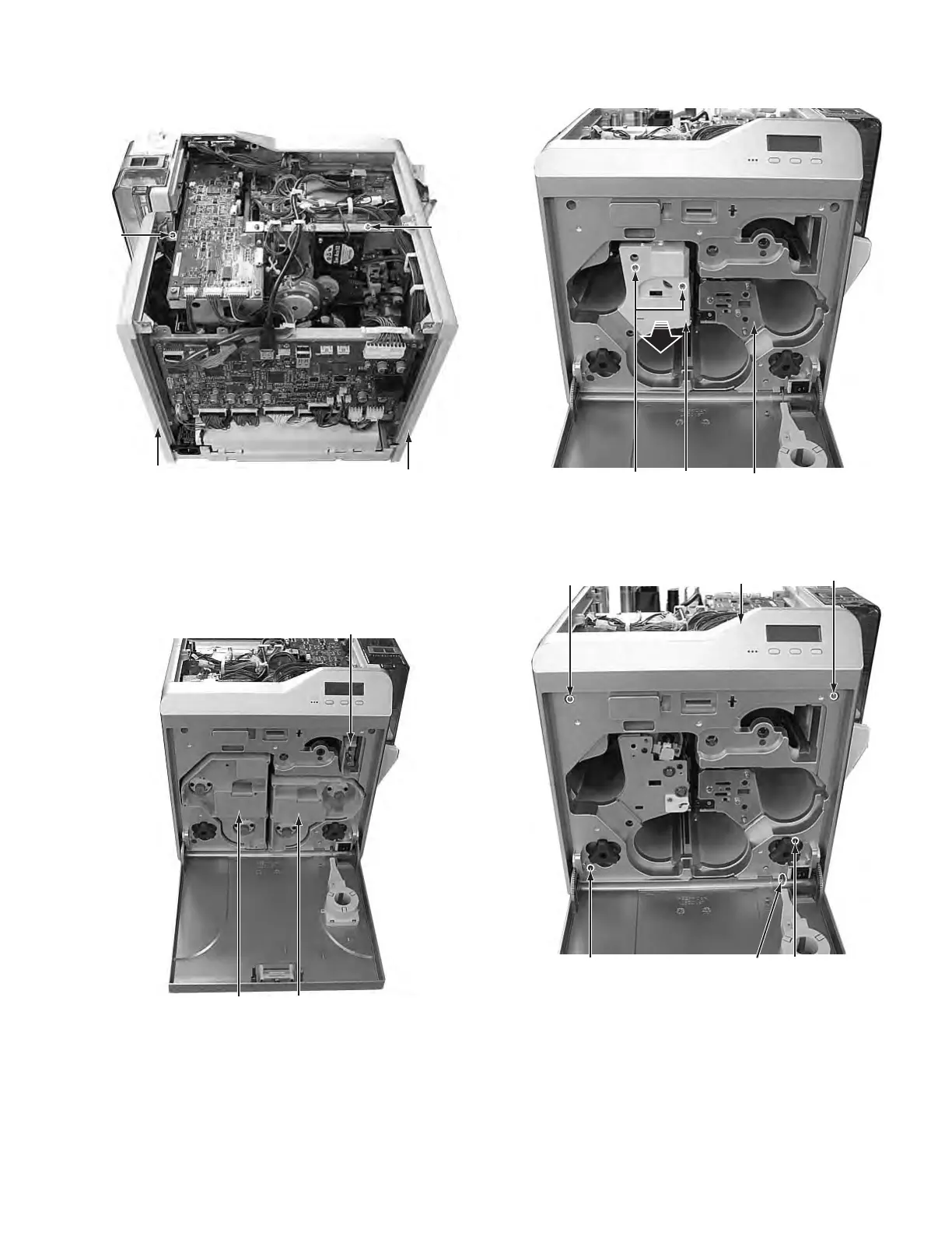
3.2 Removing the front panel unit (See figure 5 to figure
12)
(1) Remove the Media F CA unit, the Ink F CA unit, and the CL
Roller unit.
Fig.5
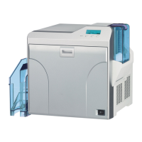
(2) Remove the two screws D attaching the cover, then re-
move the cover.
Fig.6
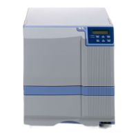
(3) Remove the four screws E attaching the front panel unit.
• Be careful not to break the cable.
Fig.7
C
C
Side cover U-R
Side cover U-L
CL Roller unit
Ink F CA unit
Media F CA unit
D
Cover
Head unit
E
E
E
Front panel unit
Cable
E