Do you have a question about the DOD rubberneck and is the answer not in the manual?
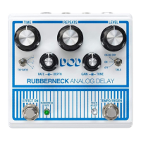
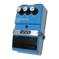
Lists the key features of the Rubberneck Analog Delay pedal.
How to adjust delay time using the footswitch and tap ratio.
Feature for stretching or compressing delay time using the footswitch.
Momentary activation of secondary feedback control for oscillation effects.
Using the loop jack to add effects to the feedback path.
Controls effect on/off and enables Rubbernecking when held.
Controls the rate of time stretching and indicates pedal status.
Controls for delay time, modulation speed/depth, and tap ratio.
Controls for delay repeats, oscillation, gain, and tone adjustments.
Controls for output level and tail behavior during bypass, plus secondary repeat control.
Taps tempo and enables secondary feedback control when held.
Connections for guitar input and amplifier output.
Jacks for external effects and footswitch control.
Port for connecting the required 9VDC power adapter.
Connect the appropriate 9VDC power supply to the unit.
Connect the pedal to the amplifier for sound output and adjust volume.
Diagram showing a direct connection between guitar, pedal, and amplifier.
Diagram showing connection via an amplifier's effects loop.
| Type | Analog Delay |
|---|---|
| Tap Tempo | Yes |
| Modulation | Yes |
| True Bypass | Yes |
| Outputs | 1 x 1/4" |
| Input Impedance | 1 MOhm |
| Output Impedance | 1 kOhm |
| Controls | Time, Repeats, Level, Tone, Gain, Rate, Depth |
| Power Supply | 9V DC |
| Inputs | 1 x 1/4" |