the
reference
signal is
input to A and a
variable
signal
Fv
to
B,
and the
FFr compares
Fr
and
Fv
to output a
coarse
PLL
signal. Tr
and
Tz are
time lags
to test
Fr
)
Fv
and
Fr
(
Fv, respectively. Flip-flop FF2 deter-
mines whether
to
place
the CPM in stop or apply
PLL
drive to it. Time Iag Ts tests
Fr) Fv,
while
flip-flop
FF3
determines whether to
accelerate
the CPM or
apply
PLL
drive
to
it.
@
Priority
sequence logic in
PLL
(time
lags Tr, Tz
and
Te)
Setting the
number of
Fv
pulses
in an Fr
cycle as
Nv,
and the
number
of
Fr
pulses
in an
Fv
cycle as Nr, then
Fr)2
Nv=0
whenFrlFv
Nr)2 Nr=0 whenFr(Fv
Nr)
2
when
Fr
) Fv
Nr=Nv=1 whenFr=Fv
1)
When Nr
=
Nv =
1,Tt
and Tz
lock
gate
outputs D and
E
to H
(High).
When Nr )2,It and T2 cause
gate
D to output an
NrJ
number
of
"L"
pulses.
But when
Nv
) 2,
they cause
gate
E
to
output an
Nv-1 number of
"L"
pulses.
These
gate
outputs are
used by
flip-flop FFz
to
determine whether to stop
the CPM or apply
PLL drive to it.
2) When
Nv =
0 and
Nr
)>
2,
gate
N outputs
an
Nrl number
of
"L"
pulses
to
set
flip-flop FFg into
accele-
ration mode.
Next, when Nv is Nv )
2,
flip-flops FFz
and
FFs
are
reset
so that
Fv
starts decreasing.
When Nr
)
2,
the
FG
frequency Fv varies
very slowly according to the
inertial
moment,
with the
motor
rotating at
a
frequency
slightly
lower
than the
synchronization
frequency.
ln order
to avoid setting
flip-flop FFs
when
Nr ) 2 and
accelerating
the
motor, flip-flop FFg is
forced
to reset by
time
constant
T3
for
the
period
from
when
the
PLL
control is started to
when Nr
=
Nv
=
1
is
established.
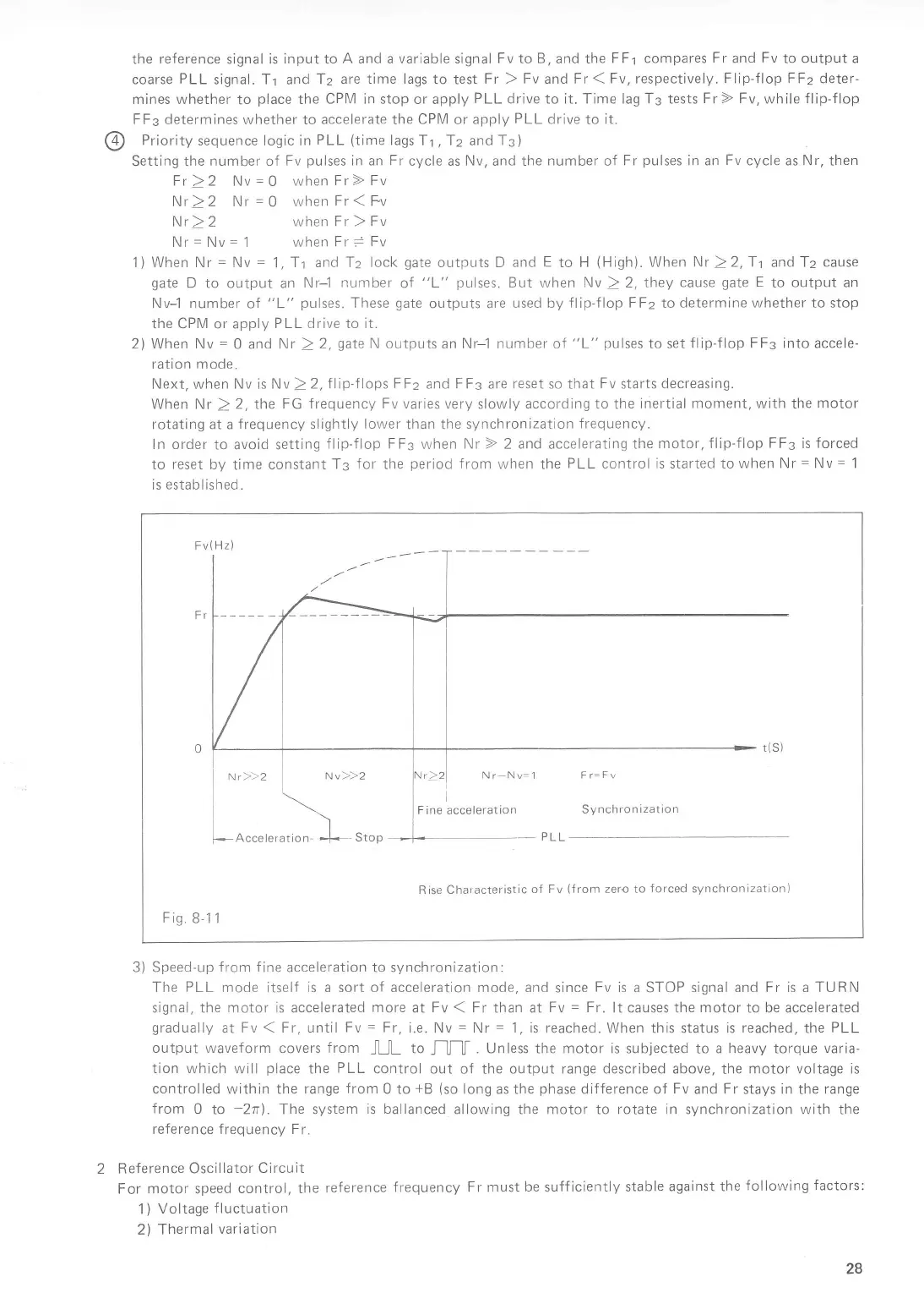
Nr)}2
Nvz)2
Acceteration-
f
,,oo
Synchronization
Rise Characteristic
of
Fv
(from
zero
to
forced
synchronization)
B-1 1
3) Speed-up
f
rom
f
ine acceleration to synchronization:
The
PLL
mode
itself
is a sort of acceleration mode, and
since
Fv
is a
STOP signal
and Fr is a TURN
signal, the motor is accelerated
more
at Fv
(
Fr
than
at
Fv
=
Fr.
lt causes the motor to be accelerated
gradually
at
Fv
(
Fr, until
Fv
=
Fr,
i.e. Nv
-
Nr
=
1,
is
reached. When this status is
reached.
the
PLL
output waveform
covers
from
JUL
to
J-]J-]I
. Unless
the
motor is
subjected to
a heavy torque varia-
tion which
will
place
the
PLL
control
out of the output range
described
above, the
motor voltage is
controlled
within the range
from
0
to
+B
(so
long
as the
phase
difference of
Fv
and
Fr
stays
in
the
range
from
0
to
-2n1
.
The system
is ballanced
allowing the motor
to
rotate in synchronization with
the
reference frequency F
r.
Reference Oscil
lator Circuit
For
motor
speed
control, the
reference
frequency Fr must
be
sufficiently
stable
against the
following
factors:
1)
Voltage
fluctuation
2)
Thermal
variation
v
28