DOLMAR GmbH
14
2
1
4
3
6
5
7
8
9
9
9
6
11
10
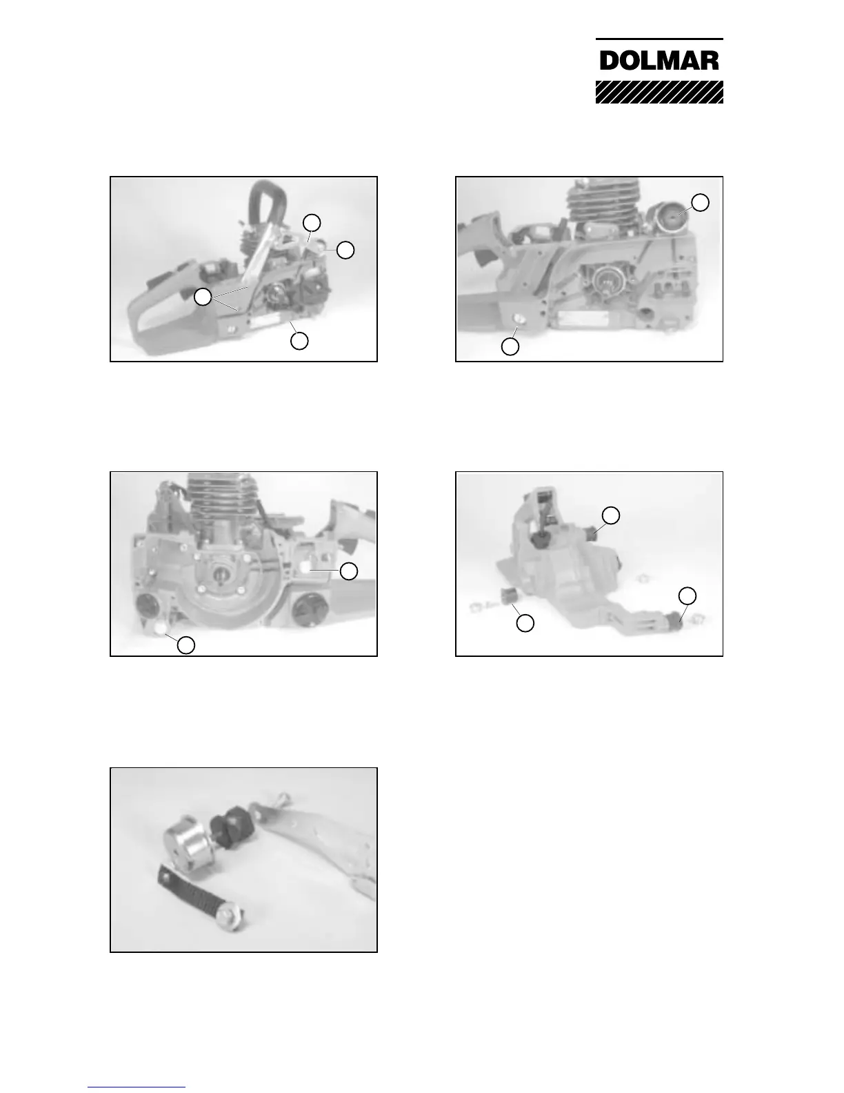
08-02 Replacing the vibration damper (KS)
Unscrew screws (5), (3) + (4). Always use
special tool, no. 944 500 621 when removing
or fitting vibration dampers (6).
08-02 Damping system design
Three identical vibration dampers (9) are
provided on the tank housing.
08-03 Damper system design
The fourth vibration damper (6) with pot (10)
and catching band (4) is located between the
supporting web (11) and the crankcase.
08-01 Removing and fitting the handle
For the removal of the handle unscrew
(1) 2 x tank screws (lateral)
(2) 2 x tank screws (bottom)
(3) 1 x vibration damper
(4) catching band.
08-02 Replacing the vibration damper (MS)
Remove screws (7) + (8), and using a Torx
spanner unscrew the screws located under-
neath.
Note: screw(8) is located under the auxiliary
filter.
08 Vibration damping system, handle