Preparation of assembly superstructure
For each Sigma Plus contract you receive a sheet with tables of assembly super-
structures of the cylinders. If positions of core and body pins are not stated in the ta-
ble ex works please enter the pins in the table.
The following shall apply:
The FB body pins may only be assembled at the first five positions, maximally 2
at each side of the cylinder.
FB body pins are assemble to the positions with the lowest values. In case of su-
perstructures (master key system), the lowest value including the superstructure is
considered.
Only N pins are available as core pins for the lengths of 0, 1, 2, 3, and for the
lengths 4, 5, 6, 7 only AB pins are available. There is no restriction of the positions
for core pins. The core pins are applied at positions P1 – P6 depending on their
lengths.
Assembly without masterkey wafers
Body pins
4 5 1 2 3 5
FB FB
P1 P2 P3 P4 P5 P6
4 5 1 2 3 5
N N FB FB N N
P1 P2
P3 P4
P5 P6
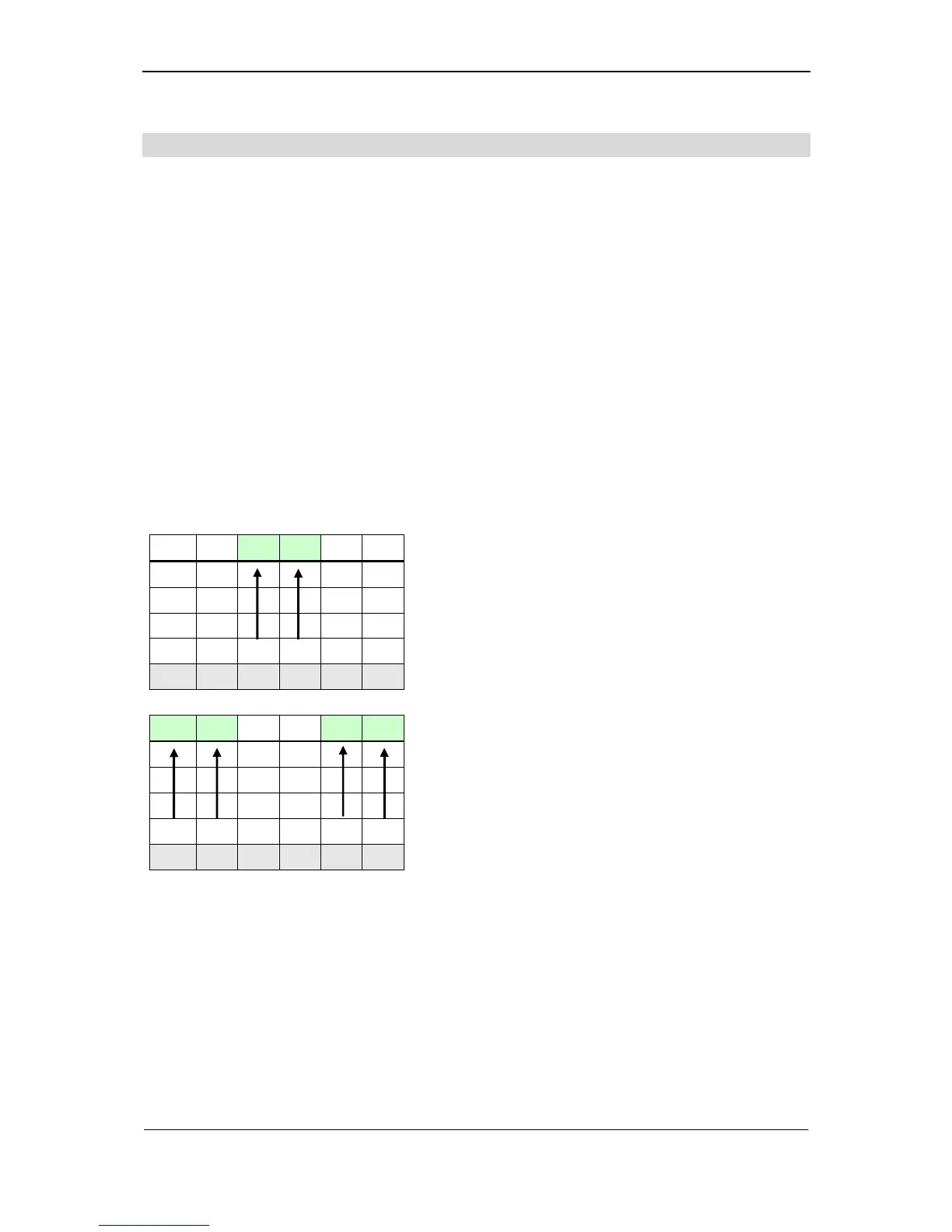
1.) At first the two FB-body pins are inserted at
the positions P1 – P5 with the lowest val-
ues.
(here: position P3=value 1 and P4=value 2)
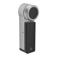
2.) N-pins are inserted at the remaining posi-
tions.