Sigma Plus Assembly / Filling of cylinder body
15
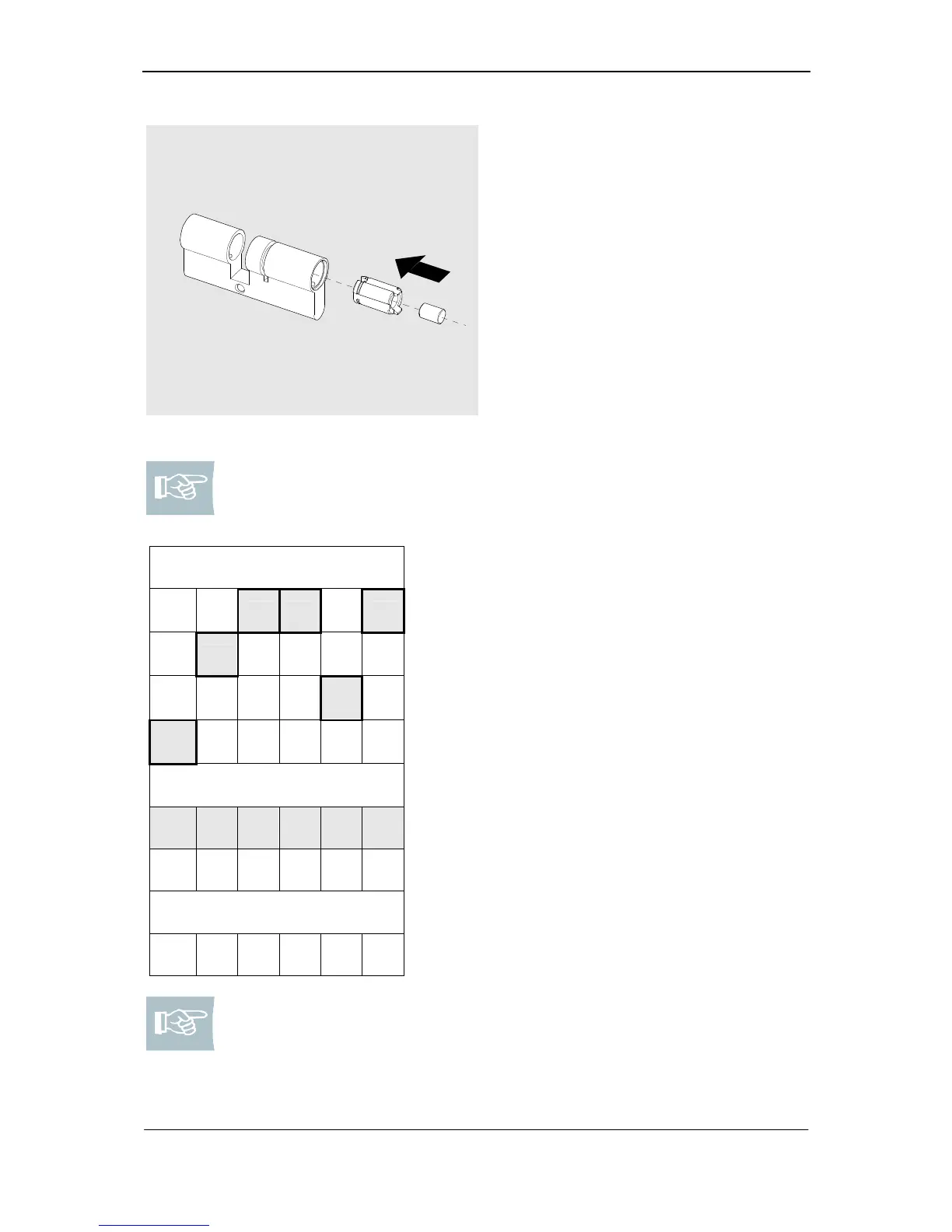
Fig. 2: Insert extension piece
1. If necessary please insert a core
extension piece with the appropriate
cylinder pin.
Note! Please hold the table of assembly superstructure ready. The body
pins are always stated in the last cell of a column. The following table of
assembly superstructure shows the body pins highlighted in grey.
Body pins
0 3 1 4 1 6
2 5
4 5
6
Example
N N FB
N N
P1 P2 P3 P4 P5 P6
Type 382
H H H H H H
0 – 3: 509264 112 = 5,5 mm
4 – 7: 509265 112 = 4,5 mm
0 – 3: 509268 112 = 5,5 mm
4 – 7: 509269 112 = 4,5 mm
0: 509271 = 5,6 mm
1: 509271 = 5,6 mm
2: 509272 = 4,6 mm
3: 509272 = 4,6 mm
4: 509273 = 4,1 mm
5: 509273 = 4,1 mm
6: 509274 = 3,1 mm
7: 509274 = 3,1 mm
Note! When using hollow body pins (type 382) the corresponding N and
FB-body pins are inapplicable.