Caution! Position and number of pin types are prescribed:
FB-body pins: On each lock side two FB-body pins are inserted. FB-
pins may only be assembled at positions P1 – P5. The FB-body pins
have to be inserted on the positions with the lowest values (here P3
and P4).
N-body pin: On each lock side at least four N-body pins are inserted.
Note! The pins mentioned in the table, read from left to right, have to be
inserted on the follower from inside to outside.
inside
6
N
5
N
1
FB
4
FB
5
N
N
6
outside
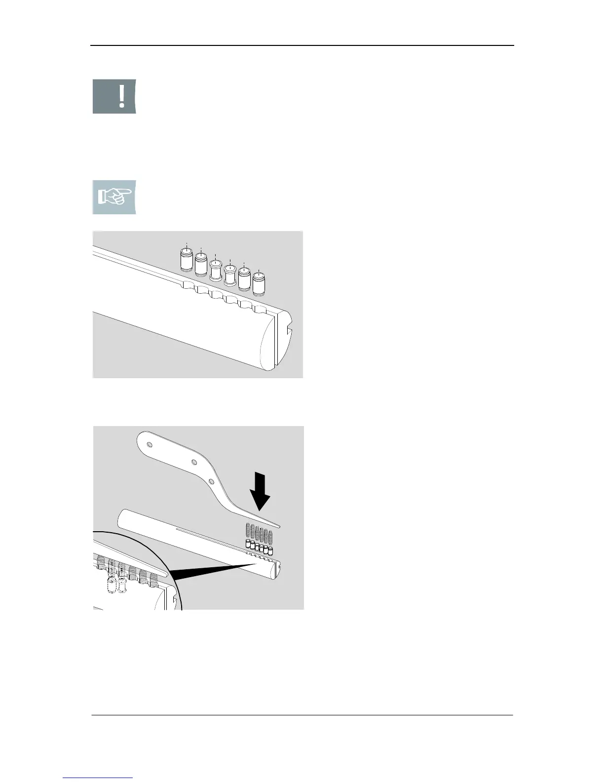
Fig. 3: Cylinder assembly superstructure
body pins
2. Please select the necessary body
pins.
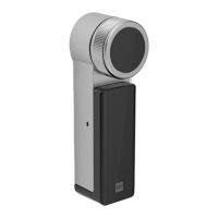
Fig. 4: Filling of follower
3. Please insert the body pins into
follower correspondingly to the de-
fined position.
4. Please apply compression springs
(242172) on the pins.
5. Using the loading knife, insert the
springs into the follower to such an
extent until the knife provides flush
fit with the follower.