10
c. Place divider plate up to bottom of air condi-
tioner base pan firmly. The foam tape on the
divider plate must seal to bottom of base pan.
See FIG. 17.
b. Remove return air cover and ceiling template
from the 3105007.XXX or 3105935.XXX kit car-
ton.
c. Locate the four 8" x 1/4" x 20 unit mounting
bolts, junction box cover and Romex connec-
tor in the 3107180.006 bolt kit.
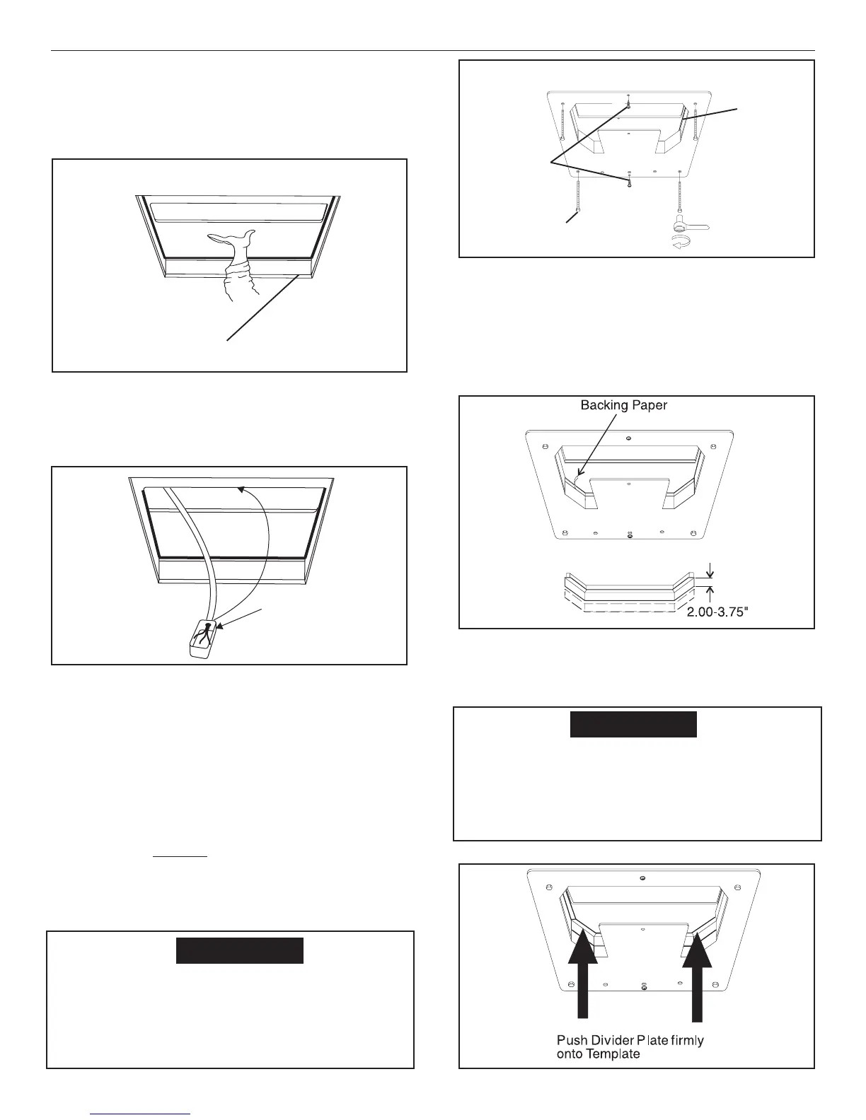
d. Reach up into the return air opening and pull
the unit electrical cord down. Mount the junc-
tion box with screws to the framing in front of
the 14-1/4" x 14-1/4" (±1/8") opening . See FIG.
15.
e. Install the Romex connector in the junction box.
f. Hold the ceiling template up to the 14-1/4" x
14-1/4" (±1/8") opening. Be sure the large plate
faces the rear of the RV.
• Start each mounting bolt through the ceil-
ing template and up into the unit base pan
by hand. Install wood screw in each end of
the ceiling template. This insures a tight fit
of the return air cover to ceiling. See FIG.
16.
• EVENLY tighten the bolts to a torque of
40 to 50 inch pounds. This will compress
the roof gasket to approximately 1/2".
The bolts are self locking so over tight-
ening is not necessary. See FIG. 16.
FIG. 14
Center Unit From Below
Roof
Gasket
If bolts are left loose there may not be ad-
equate roof seal or if over tightened, damage
may occur to the air conditioner base or ceil-
ing template. Tighten to specifications listed
in this manual.
CAUTION
FIG. 17
Improper installation and sealing of divider
plate will cause the compressor to quick cycle
on the cold control. This may result in fuse or
circuit breaker opening and/or lack of cool-
ing.
FIG. 18
FIG. 15
Fasten Junction Box
To Front Of Opening
FIG. 16
Finger
Tight
Front of Vehicle
Tighten to
compress gasket
to 1/2"
Roof
Gasket
Screws
2. Installation Of Divider Plate
a Measure the ceiling to roof thickness:
• If distance is 2.0" - 3-3/4", remove perfo-
rated tab from divider plate.
• If distance is 3-3/4" - 5-1/2", remove no tabs.
b. Remove the backing paper from double sided
tape located on ceiling template. See FIG. 17.
620515, 620525, 620526, 630515 & 630516 Installation Instructions