EasyManua.ls Logo

Dometic DOTR12CSIV - Wire Color

Dometic DOTR12CSIV
46 pages
Print Icon
To Next Page IconTo Next Page
To Previous Page IconTo Previous Page
Loading...
7-7
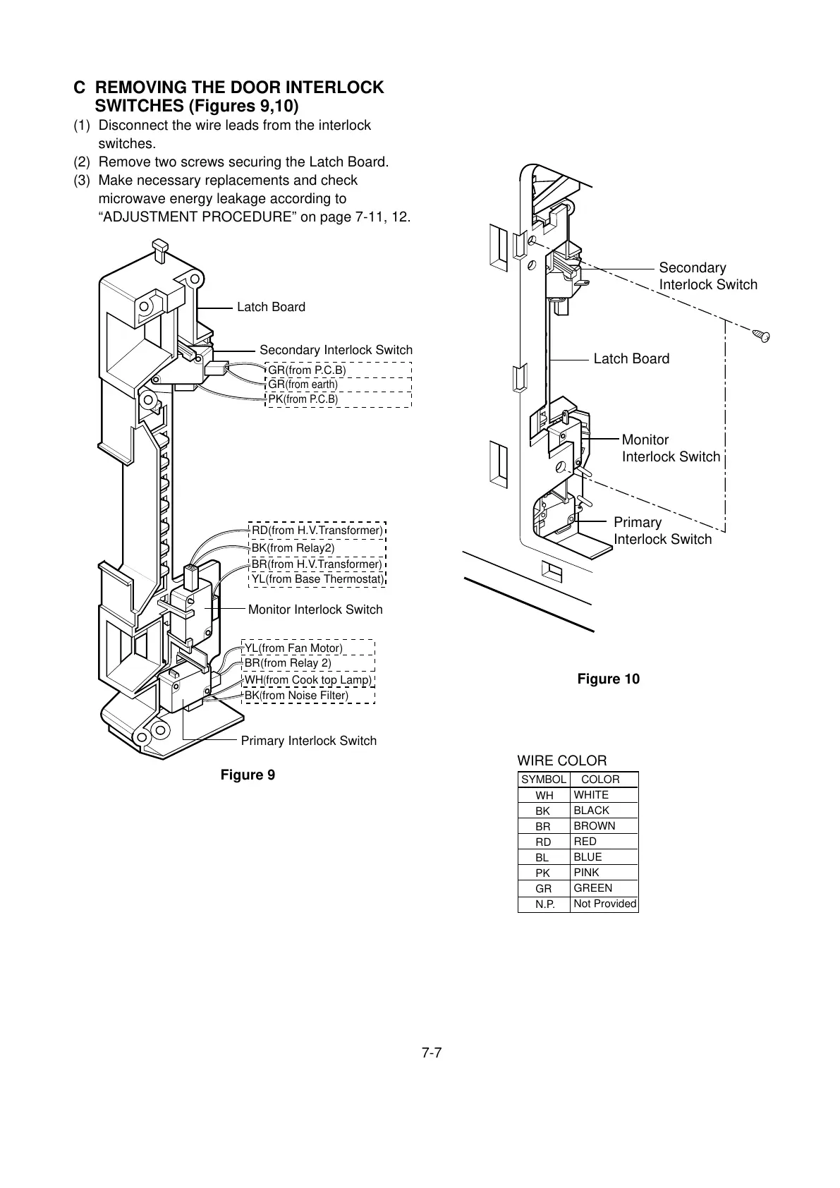
C REMOVING THE DOOR INTERLOCK
SWITCHES (Figures 9,10)
(1) Disconnect the wire leads from the interlock
switches.
(2) Remove two screws securing the Latch Board.
(3) Make necessary replacements and check
microwave energy leakage according to
“ADJUSTMENT PROCEDURE” on page 7-11, 12.
Latch Board
Secondary
Interlock Switch
Monitor
Interlock Switch
Primary
Interlock Switch
Latch Board
GR(from P.C.B)
GR
(from earth)
PK
(from P.C.B)
Secondary Interlock Switch
Monitor Interlock Switch
Primary Interlock Switch
BR(from Relay 2)
YL(from Fan Motor)
WH
(
from Cook top Lamp)
BK
(
from Noise Filter)
BR(from H.V.Transformer)
BK(from Relay2)
YL(from Base Thermostat)
RD(from H.V.Transformer)
Figure 9
Figure 10
WIRE COLOR
SYMBOL COLOR
WH
BK
BR
RD
BL
PK
GR
N.P.
WHITE
BLACK
BROWN
RED
BLUE
PINK
GREEN
Not Provided

Related product manuals